CES-I-BR-CC-FLX-C07-SA-165914 (Order no. 165914)
Safety switch CES-I-BR-CC-FLX-C07, RFID, plug connector(s) M12
- Suitable for actuator with same coding
- Door position monitoring output/communication OD/C
- Diagnostic information via BR/IO-Link gateway
- Plug connector M12, 8-pin
Description
Actuators with the same coding
The actuators of a packaging unit must be assigned to the safety switch by a teach-in operation so that they are detected by the system. This unambiguous assignment ensures a particularly high level of protection against tampering. The system thus possesses a high coding level.
The coding is identical for all the actuators in a packaging unit. Actuators from different packaging units are coded differently. Only one actuator from a packaging unit has to be taught-in. All other actuators from the same package can be used without an additional teach-in operation.
The switch detects only taught-in actuators. When an actuator from a new packaging unit is taught-in, the code for actuators from the previous packaging unit is disabled.
Approach direction and installation position
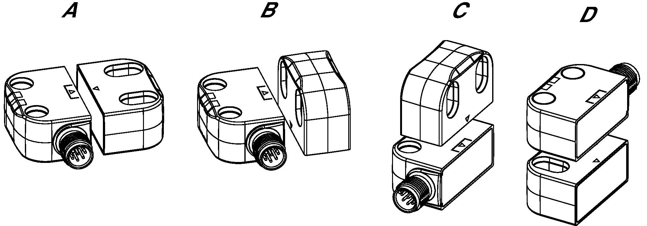
Permissible installation position
Typical operating distance
(Only in conjunction with actuator CES-A-BTN-C07)
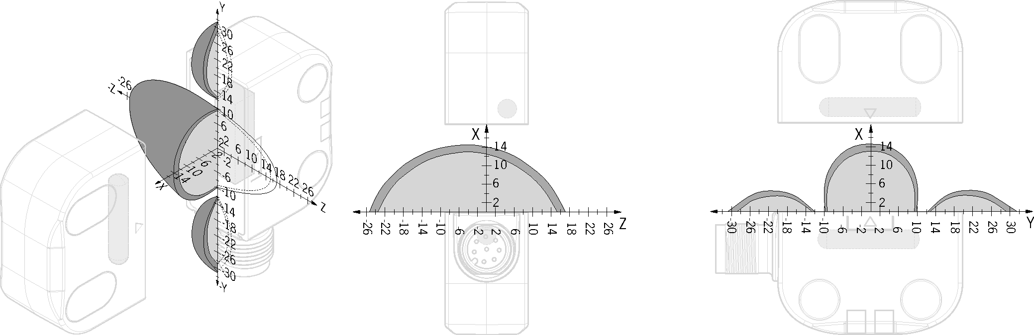
For a side approach direction for the actuator and safety switch, a minimum distance of s = 6 mm must be maintained so that the actuating range of the side lobes is not entered.
Attention:
The actuating range may vary depending on the actuator, substrate material and installation situation. Further actuating ranges can be found in the operating instructions.
Highly coded evaluation
Each actuator is highly coded. The switch only recognizes learned actuators. Further actuators can be taught.
Only the last actuator taught-in is detected.
Category according to EN 13849-1
Due to two redundantly designed semiconductor outputs (safety outputs) with internal monitoring suitable for:
- Category 4/PL e according to EN 13849-1
Important: To achieve the stated category according to EN ISO 13849-1, both safety outputs (FO1A and FO1B) must be evaluated.
Industry 4.0 ready
The switch can communicate in combination with an EUCHNER BR IO-Link Gateway, and sends process and device data to higher-level control systems. Comprehensive diagnostic messages enable rapid and targeted troubleshooting.
LED indicator
STATE | Status LED |
DIA | Diagnostics LED |
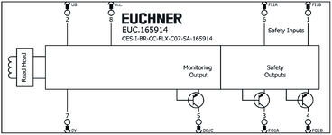
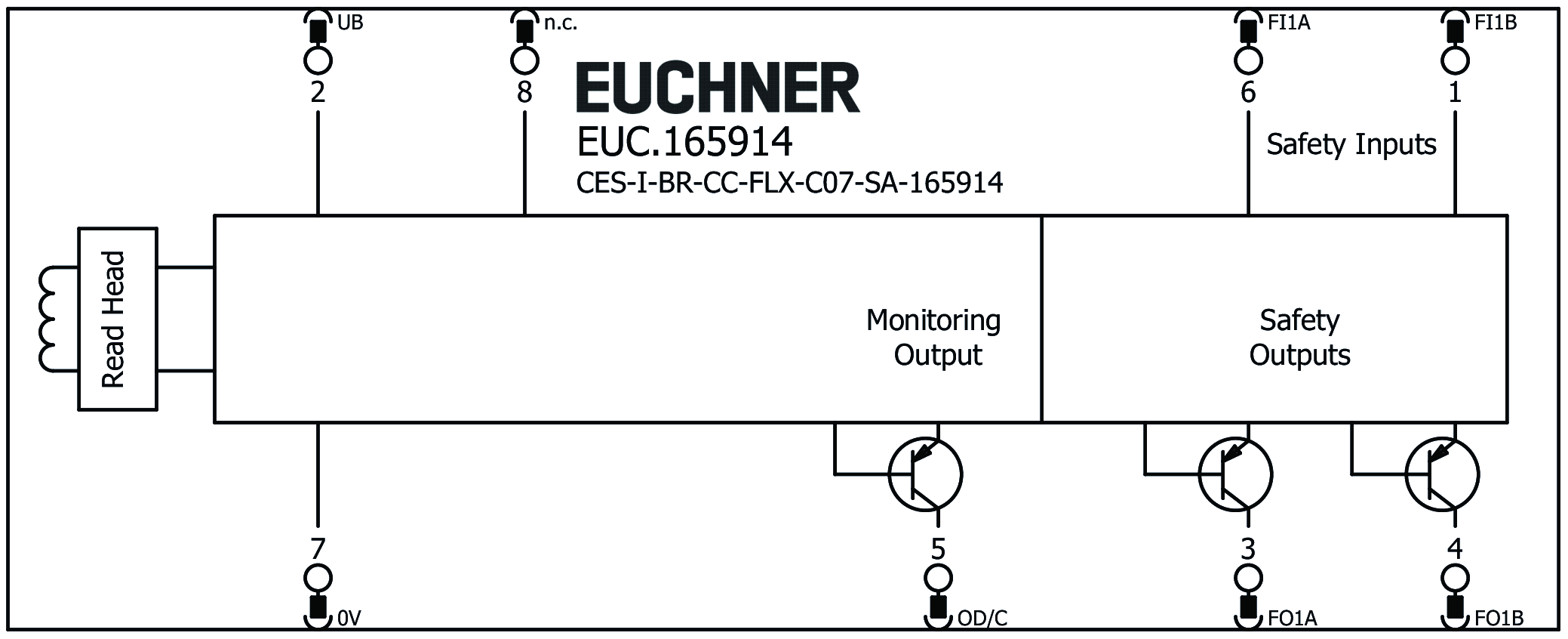
Terminal assignment
| Plug connector (view of connection side) | Pin | Designation | Function |
|---|---|---|---|
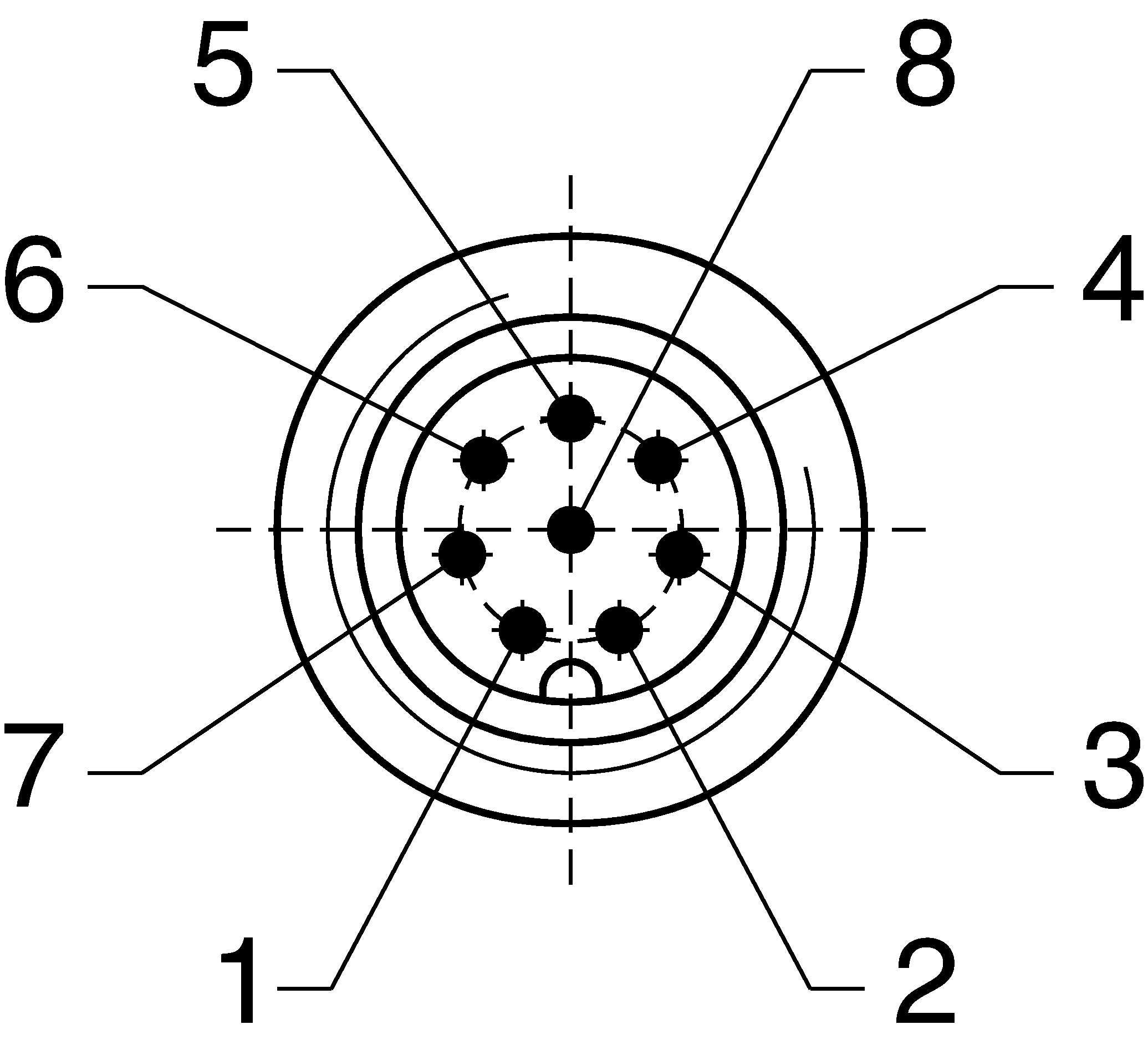 | 1 | FI1B | Enable input, channel B |
| 2 | UB | Electronics operating voltage, 24 V DC | |
| 3 | FO1A | Safety output, channel A | |
| 4 | FO1B | Safety output, channel B | |
| 5 | OD/C | Door position monitoring output/communication | |
| 6 | FI1A | Enable input, channel A | |
| 7 | 0 V | Weight 0 V DC | |
| 8 | nc | n.c. |
Plug connector(s) adjusted C07
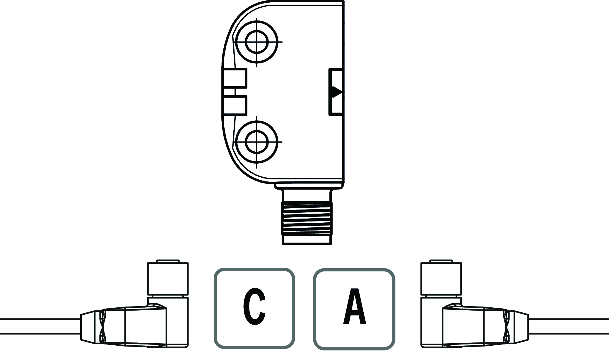
The following applies for the installation position of the device shown: cable outlet C (left), cable outlet A (right).
Scope of delivery
- Cover caps for the mounting holes
Accessories required
Actuator is not included.
The safety switch can only be actuated in conjunction with the actuators provided for this purpose.
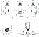
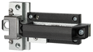
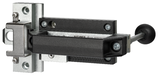
Dimensional drawings
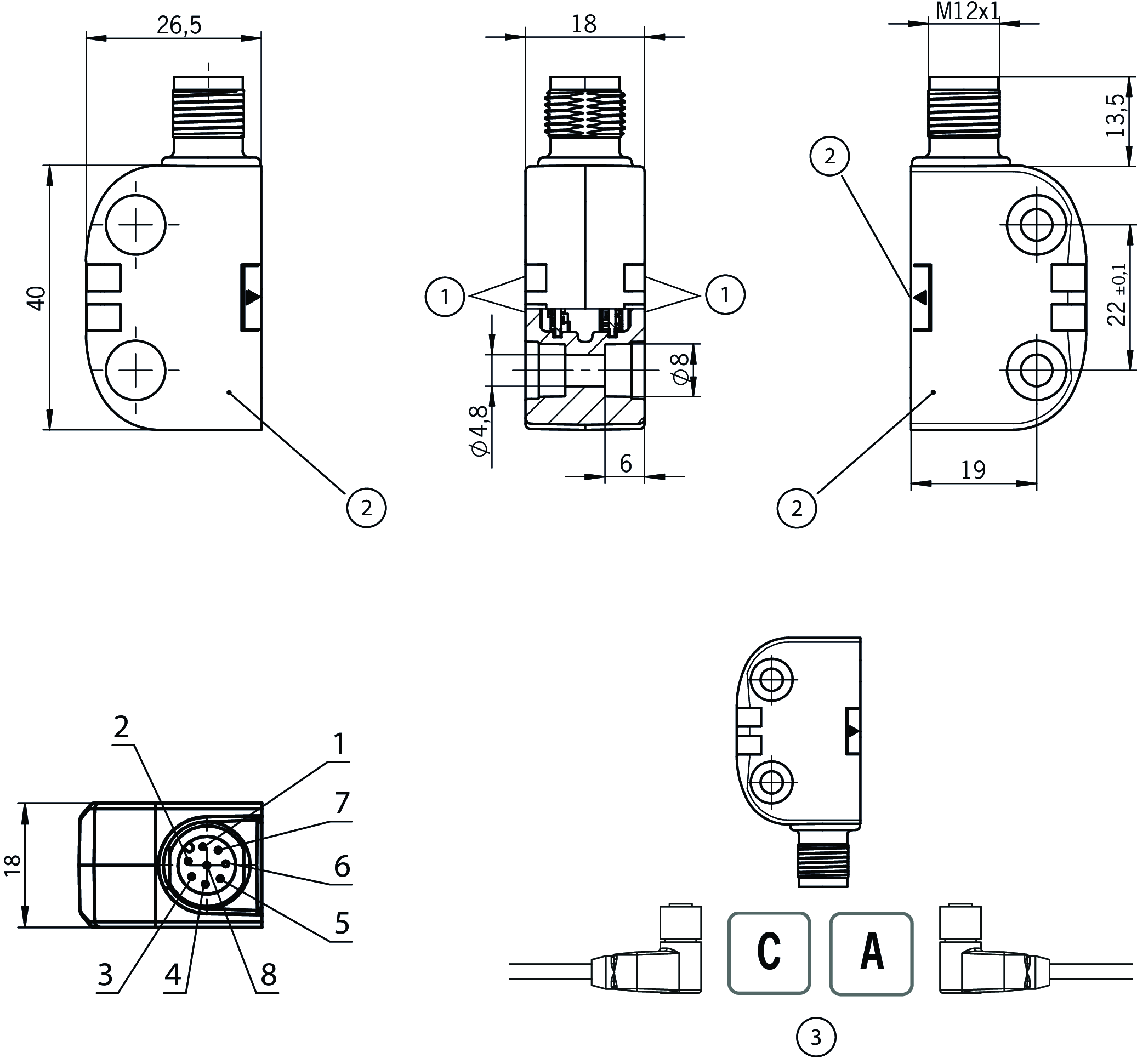
| 1 | LEDs |
| 2 | Active face |
| 3 | With the installation orientation shown: cable outlet on left or right |
Connection examples
Technical data
Approvals


Workspace
| Repeat accuracy R | |
| according to EN 60947-5-2 | 10 % |
Electrical connection values
| Fuse | |
| external (operating voltage) | 0.25 ... 8 A |
| rated conditional short-circuit current | 100 A |
| Rated insulation voltage Ui | 75 V |
| Rated impulse voltage Uimp | 1.5 kV |
| Operating voltage DC | |
| UB | 24 V DC -15% ... +15% regulated, residual ripple<5%, PELV |
| Turn-on time | |
| Safety outputs | max. 100 ms |
| EMC protection requirements | Acc. to EN IEC 60947-5-3 |
| Risk time according to EN 60947-5-3 | max. 125 ms |
| Risk time according to EN 60947-5-3, extension for each additional device | max. 10 ms |
| Safety class | III |
| Current consumption | 40 mA |
| Degree of contamination (external, according to EN 60947-1) | 3 |
| Monitoring output OD/C | |
| Output type | p-switching, short circuit-proof |
| Output voltage | UB-1.5 ... UB V DC |
| Switching current | 1 ... 50 mA |
| Safety outputs FO1A/FO1B | |
| Output type | Semiconductor outputs, p-switching, short circuit-proof |
| Output voltage | |
| HIGH U(FO1A) / U(FO1B) | UB-1.5V ... UB V DC (Values at a switching current of 50 mA without taking into account the cable lengths.) |
| LOW U(FO1A) / U(FO1B) | 0 ... 1 V DC |
| Discrepancy time | max. 10 ms |
| Utilization category | |
| DC-13 | 24V 150mA (Caution: outputs must be protected with a free-wheeling diode in case of inductive loads.) |
| Off-state current Ir | max. 0.25 mA |
| Switching current | 1 ... 150 mA |
| Test pulse duration | 0.3 ms (Applies to a load with C<= 30nF and R<= 20kOhm) |
| Test pulse interval | ca 100 ms |
Mechanical values and environment
| Dimensions | 40 x 26.5 x 18 |
| Connection type | M12 plug connector, 8-pin |
| Tightening torque | max. 0.8 Nm |
| Ready delay | 5 s |
| Operating altitude | max. 4 000 m |
| Installation orientation | any |
| Switching frequency | max. 1 Hz |
| Storage temperature | -25 ... 70 °C |
| Mounting distance | |
| between switches | min. 50 mm |
| Mounting type | Surface mounting on metal |
| Shock and vibration resistance | Acc. to EN IEC 60947-5-3 |
| Degree of protection | IP65/IP67/IP69/IP69K |
| Ambient temperature | |
| at UB = 24 V DC | -25 ... 55 °C (+65 °C at IL= max. 10 mA per safety output) |
| Material | |
| Housing | Plastic, PBT-PC-GF30 |
Characteristic values according to EN ISO 13849-1 and EN IEC 62061
| Mission time | |
| according to EN ISO 13849-1 | |
| SIL CL | |
| according to EN 62061:2005/A2:2015 |
Characteristic values according to EN ISO 13849-1 and EN IEC 62061
| PL | Maximum SIL | PFHD | Category | Mission time | |
|---|---|---|---|---|---|
| Monitoring of the guard position | PL e | 3 | 6x10⁻¹⁰ | 4 | 20 y |
Miscellaneous
| Notices for UL approval | Operation only with UL Class 2 power supply or equivalent measures |
| Additional feature | Caps included |
In combination with actuator S-C07-04-V02-165928
| Switch-on distance | |
| Installation position A + B | 13 mm |
| Installation position C + D | 7 mm |
| Secured switch-off distance sar | |
| in x direction/installation position A + B | max. 20 mm |
| in x direction/installation position C + D | max. 17 mm |
| Secured switching distance sao | |
| in x direction/installation position B | min. 9 mm |
| in x direction/installation position C | min. 3 mm |
| in x direction/installation position D | min. 2 mm |
| in x direction/installation position A | min. 10 mm |
| Switching hysteresis | 1 ... 2 mm |
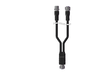
Accessories


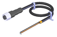
AC-YD-V0,2-SBB-158192
- For series connection of BR safety switches in switch chains with IO-Link evaluation
- Y-distributor with M12 female plug, 8-pin
- Male plug straight, 5-pin
- Female plug straight, 5-pin
- TPU housing, black
- Cable length 0.2 m / PVC
AC-YD-V1,0-SBB-158193
- For series connection of AR/BR safety switches in switch chains with ESM-CB for IO-Link evaluation
- Y-distributor with M12 female plug, 8-pin
- Male plug straight, 5-pin
- Female plug straight, 5-pin
- TPU housing, black
- Cable length 1.0 m
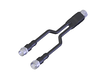
AC-YD-V0,2-SBB-111696
- For series connection of AR/BR safety switches in switch chains without IO-Link evaluation
- Y-distributor M12 with connecting cable, 2 x 5-pin, 1 x 8-pin
- Straight plug connector
- PVC cable
- Cable length 0.2 m
AC-YD-V1,0-SBB-112395
- For series connection of AR/BR safety switches in switch chains without IO-Link evaluation
- Y-distributor M12 with connecting cable, 2 x 5-pin, 1 x 8-pin
- Straight plug connector
- PVC cable
- Cable length 1 m

Downloads
Complete package
Download all important documents with a single click.
Content:
- The operating instructions and any additions to the operating instructions or brief instructions
- Any data sheets to supplement the operating instructions
- The declaration of conformity
Single Documents


Other Documents


CAD data

Ordering data
| Ordernumber | 165914 |
| Item designation | CES-I-BR-CC-FLX-C07-SA-165914 |
| Gross weight | 0,061kg |
| Customs tariff number | 85365019 |
| ECLASS | 27-27-24-03 Safety-related transponder switch |