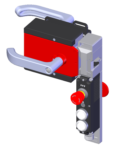
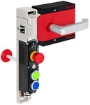
MGBS-P-L1HE-AR-U-L-SH-160521 (Order no. 160521)
MGBS set AR, M23, emergency stop, 2 pushbuttons, with escape release, door hinge on left
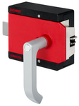
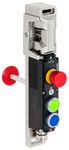
- Locking module with handle module
- suitable for doors hinged on the left
- Series connection possible (up to 20 AR devices in series)
- Short circuit monitoring
- 2 safety outputs (semiconductor outputs)
- Up to category 4 / PL e according to EN ISO 13849-1
- Emergency stop
- 2 pushbuttons (illuminated)
- With plug connector M23
- Unicode
- Door position monitoring output
- incl. escape release and inner door handle
Description
Unicode evaluation
Each handle module is highly coded (unicode). The locking module detects only handle modules that have been taught-in. Additional handle modules can be taught-in. Only the last handle module taught-in is detected.
Guard locking type
MGBS-L1 | Guard locking actuated by spring force and power-ON released (closed-circuit current principle). |
Lens set
The color of the pushbuttons can be selected using the color cover set included (5 colors).
Escape release
It is used for manual release of the guard locking without tools in an emergency. The inner door handle permits escape from the danger zone.
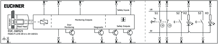
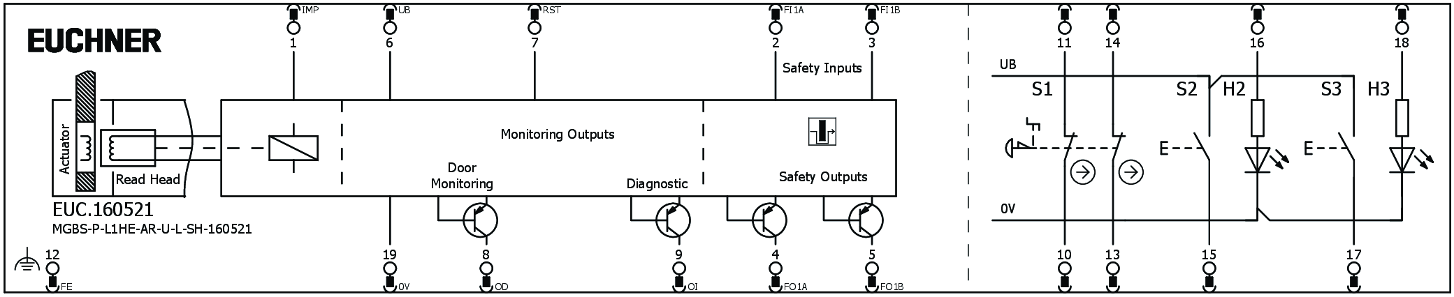
Connector assignment
| Plug connector (view of connection side) | Pin | Designation | Function | Connecting cable conductor coloring |
|---|---|---|---|---|
 | 1 | IMP | Solenoid operating voltage, 24 V DC | VT |
| 2 | FI1A | Enable input, channel A | RD | |
| 3 | FI1B | Enable input, channel B | GY | |
| 4 | FO1A | Safety output, channel A | RD/BU | |
| 5 | FO1B | Safety output, channel B | GN | |
| 6 | UB | Electronics operating voltage, 24 V DC | BU | |
| 7 | RST | Reset input | GY/PK | |
| 8 | OD | Door position monitoring output | GN/WH | |
| 9 | OI | Diagnostic monitoring output | YE/WH | |
| 10 | S1.A1 | EMERGENCY STOP (channel A) | GY/WH | |
| 11 | S1.A2 | EMERGENCY STOP (channel A) | BK | |
| 12 | FE | Functional earth (must be connected to meet the EMC requirements) | GN/YE | |
| 13 | S1.B1 | EMERGENCY STOP (channel B) | PK | |
| 14 | S1.B2 | EMERGENCY STOP (channel B) | BN/GY | |
| 15 | S2 | Pushbutton 2 (illuminated) | BN/YE | |
| 16 | H2 | LED 2 | BN/GN | |
| 17 | S3 | Pushbutton 3 (illuminated) | WH | |
| 18 | H3 | LED 3 | YE | |
| 19 | 0 V | Electronics and solenoid operating voltage, 0 V DC | BN |

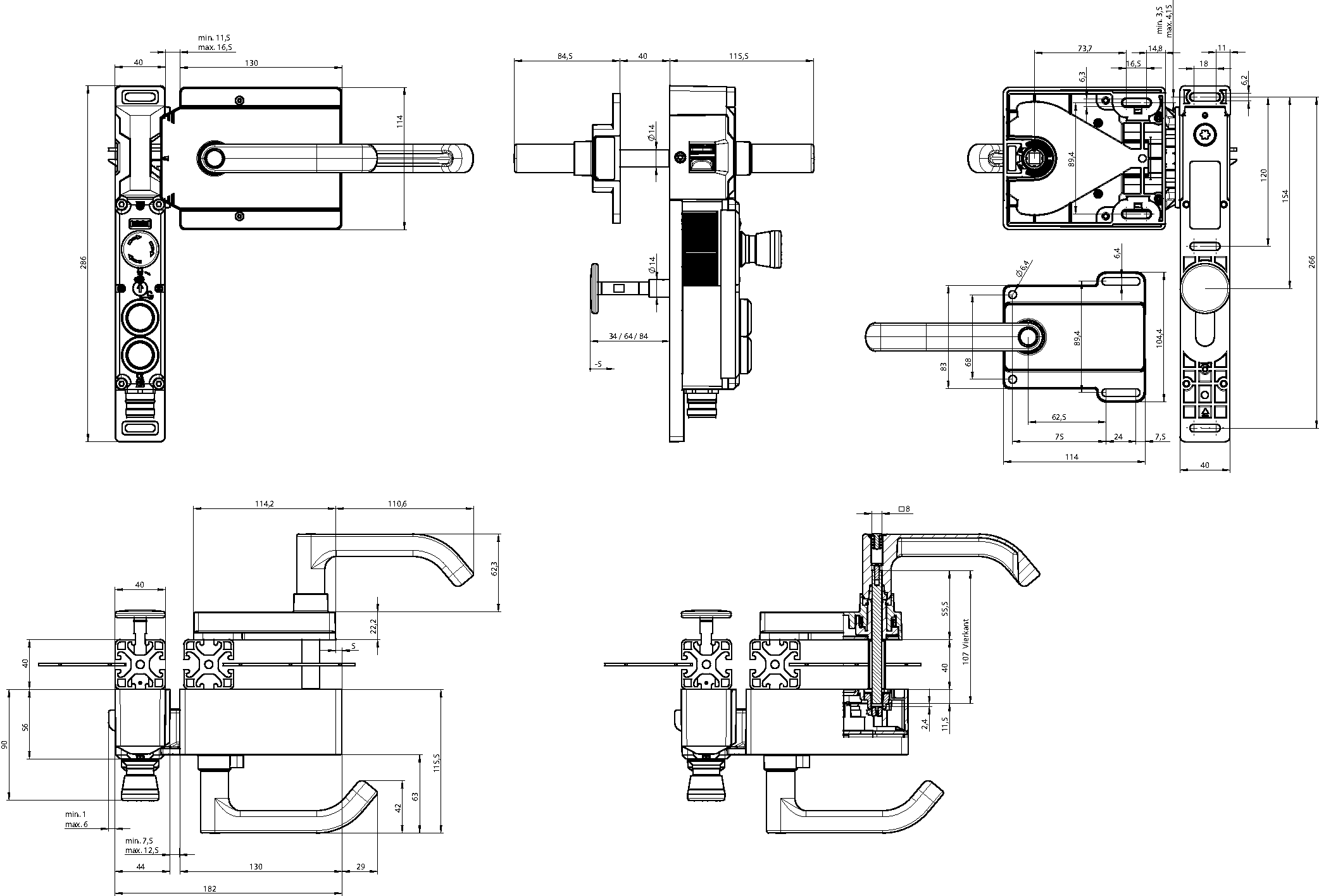
Dimensional drawings
Connection examples
Technical data
Approvals

Escape release AE-R-S1-158322 (Order no. 158322)

Mechanical values and environment
| Installation orientation | any |
| Storage temperature | -25 ... 70 °C |
| Mechanical life | 1 x 10⁶ |
| Ambient temperature | -20 ... 55 °C |
| Material | |
| Housing | Die-cast zinc, stainless steel powder-coated, brass |
Miscellaneous
| Additional feature | with silver-colored handle |
Handle modules MGBS-H-BA1A3-L-157544 (Order no. 157544)
Mechanical values and environment
| Installation orientation | Door hinge DIN left |
| Storage temperature | -25 ... 70 °C |
| Degree of protection | IP65 |
| Ambient temperature | -20 ... 55 °C |
| Material | |
| Housing | Fiber glass reinforced plastic, nickel-plated die-cast zinc, stainless steel |
Miscellaneous
| Product version number | V1.0.0 |
| Additional feature | with automatic lockout mechanism |
Locking modules MGBS-P-L1-AR-U-L-AEE-SH-160873 (Order no. 160873)
Workspace
| Repeat accuracy R | 10 % |
Operating and display elements
| Item | Color | Extras | Version | Switching element | Slide-in label | Note slide-in label | Number | Designation1 | LED |
|---|---|---|---|---|---|---|---|---|---|
| 1 | Emergency stop | 2 PD | |||||||
| 2 | Illuminated pushbutton | 1NO | |||||||
| 3 | Illuminated pushbutton | 1NO |
Electrical connection values
| Fuse | |
| external (operating voltage UB) | 0.25 ... 8 A |
| external (solenoid operating voltage IMP) | 0.5 ... 8 A |
| Power consumption | 6 W |
| Rated insulation voltage Ui | 50 V |
| Rated impulse voltage Uimp | 0.5 kV |
| Operating voltage DC | |
| UUB | 24 V DC -15% ... +15% reverse polarity protected, regulated, residual ripple<5%, PELV |
| EMC protection requirements | Acc. to EN IEC 60947-5-3 |
| Utilization category | |
| DC-13 | 24V 150mA (Caution: outputs must be protected with a free-wheeling diode in case of inductive loads) |
| Solenoid operating voltage DC | |
| UIMP | 24 V DC -15% ... +10% reverse polarity protected, regulated, residual ripple<5%, PELV |
| Solenoid duty cycle | 100 % |
| Risk time according to EN 60947-5-3 | max. 260 ms |
| Risk time according to EN 60947-5-3, extension for each additional device | max. 5 ms |
| Switching load | |
| according to UL | 24V DC, Class 2 (alternatively, see operating instructions) |
| Safety class | III |
| Current consumption | |
| IIMP | 400 mA |
| IUB | 40 mA |
| Test pulse duration | max. 1.0 ms (Applies to a load with C<= 30nF and R<= 20kOhm) |
| Test pulse interval | min. 140 ms |
| Degree of contamination (external, according to EN 60947-1) | 3 |
| Controls and indicators | |
| Operating voltage | UB V |
| Operating current | 1 ... 50 mA |
| Power supply | |
| LED | 24 V |
| Current consumption | |
| LED | 10 mA |
| Emergency stop | |
| Breaking capacity | max. 0.25 W |
| Switching voltage | 5 ... 24 V |
| Switching current | 1 ... 100 mA |
| Monitoring output OD, OI | |
| Output type | p-switching, short circuit-proof |
| Output voltage | 0.8xUB ... UB V DC |
| Switching current | 1 ... 50 mA |
| Safety outputs FO1A/FO1B | |
| Output type | 2 semiconductor outputs, p-switching, short circuit-proof |
| Output voltage | |
| HIGH U(FO1A) / U(FO1B) | UB-1.5 ... UB V DC |
| LOW U(FO1A) / U(FO1B) | 0 ... 1 V DC |
| Discrepancy time | |
| both safety outputs | max. 10 ms Acc. to EN IEC 60947-5-3 |
| Turn-on time | max. 400 ms |
| Off-state current Ir | max. 0.25 mA |
| Switching current | |
| per safety output FO1A / FO1B | 1 ... 150 mA |
Mechanical values and environment
| Anfahrgeschwindigkeit | max. 20 m/min |
| Connection type | 1 plug connector M23, 19-pin, RC18 |
| Extraction force | 20 N |
| Ready delay | 8 s |
| Actuating force | 10 N |
| Installation orientation | Door hinge DIN left |
| Switching frequency | max. 0.5 Hz |
| Storage temperature | -25 ... 70 °C |
| Mechanical life | 1 x 10⁶ |
| Overtravel | 5 mm |
| Retention force | 20 N |
| Shock and vibration resistance | Acc. to EN IEC 60947-5-3 |
| Degree of protection | IP65 (In the inserted and screwed tight state) |
| Ambient temperature | |
| at UB = 24 V DC | -20 ... 55 °C |
| Material | |
| Switch bracket | Die-cast zinc |
| Safety switch housing | Reinforced thermoplastic |
| Locking force Fmax | 3900 N |
| Locking force FZh | 3000 N (Fzh = Fmax/1.3, depending on the actuator used) |
| Guard locking principle | Closed-circuit current principle |
Characteristic values according to EN ISO 13849-1 and EN IEC 62061
| PL | Maximum SIL | PFHD | Category | Mission time | |
|---|---|---|---|---|---|
| Guard lock monitoring | PL e | - | 4.1x10⁻⁹ | 4 | 20 y |
| B10D | Mission time | |
|---|---|---|
| Emergency stop | 0.13x10⁶ | 20 y |
| PL | Maximum SIL | Category | Mission time | |
|---|---|---|---|---|
| Control of guard locking | Depending on external control of guard locking | 20 y | ||
Miscellaneous
| Notices for UL approval | Operation only with UL Class 2 power supply or equivalent measures; see operating instructions |
| Additional feature | |
| incl. lens set, ID no. 120344 | |
| Escape release actuated by pushing |
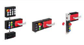
Components
AE-R-S1-158322
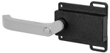
Inner door handle AE-R-S1
- Inner door handle silver colored
- A sticker describing the opening sequence is included with the locking module
- Extended actuation axis for thicker doors (order separately)

MGBS-H-BA1A3-L-157544
Handle module MGBS-H-BA1A3-L
- Intelligent bolt tongue
- Door hinge on left (not adjustable)
- Automatically extending lockout mechanism
- Door handle
MGBS-P-L1-AR-U-L-AEE-SH-160873
MGBS-AR, M23, emergency stop, 2 pushbuttons, with escape release, door hinge on left
- Locking module (order handle module separately)
- Adjustable door hinge; factory setting: left. The door hinge on left option cannot be ordered separately. Order as spare part 159086.
- Series connection possible (up to 20 AR devices in series)
- Short circuit monitoring
- 2 safety outputs (semiconductor outputs)
- Up to category 4 / PL e according to EN ISO 13849-1
- Emergency stop
- 2 pushbuttons (illuminated)
- With plug connector M23
- Unicode
- Door monitoring output
- With escape release (order inner door handle separately)
Accessories
C-M23F19-19XDIFPU01,5-MA-092906
- M23 plug connector, 18-pin + PE
- Angled plug connector
- Cable exit C (left)
- PUR cable
- Cable length 1.5 m
- With flying lead
- Cores color-coded
C-M23F19-19XDIFPU01,5-MA-092907
- M23 plug connector, 18-pin + PE
- Angled plug connector
- Cable exit A (right)
- PUR cable
- Cable length 1.5 m
- With flying lead
- Cores color-coded

C-M23F19-19XDIFPU10,0-MA-092901
- M23 plug connector, 18-pin + PE
- Angled plug connector
- Cable exit C (left)
- PUR cable
- Cable length 10 m
- With flying lead
- Cores color-coded
C-M23F19-19XDIFPU10,0-MA-092902
- M23 plug connector, 18-pin + PE
- Angled plug connector
- Cable exit A (right)
- PUR cable
- Cable length 10 m
- With flying lead
- Cores color-coded
C-M23F19-19XDIFPU15,0-MA-077020
- M23 plug connector, 18-pin + PE
- Angled plug connector
- Cable exit C (left)
- PUR cable
- Cable length 15 m
- With flying lead
- Cores color-coded
C-M23F19-19XDIFPU15,0-MA-085196
- M23 plug connector, 18-pin + PE
- Angled plug connector
- Cable exit A (right)
- PUR cable
- Cable length 15 m
- With flying lead
- Cores color-coded
C-M23F19-19XDIFPU20,0-MA-092910
- M23 plug connector, 18-pin + PE
- Angled plug connector
- Cable exit C (left)
- PUR cable
- Cable length 20 m
- With flying lead
- Cores color-coded
C-M23F19-19XDIFPU20,0-MA-092911
- M23 plug connector, 18-pin + PE
- Angled plug connector
- Cable exit A (right)
- PUR cable
- Cable length 20 m
- With flying lead
- Cores color-coded
C-M23F19-19XDIFPU25,0-MA-092912
- M23 plug connector, 18-pin + PE
- Angled plug connector
- Cable exit C (left)
- PUR cable
- Cable length 25 m
- With flying lead
- Cores color-coded
C-M23F19-19XDIFPU25,0-MA-092913
- M23 plug connector, 18-pin + PE
- Angled plug connector
- Cable exit A (right)
- PUR cable
- Cable length 25 m
- With flying lead
- Cores color-coded
C-M23F19-19XDIFPU03,0-MA-092908
- M23 plug connector, 18-pin + PE
- Angled plug connector
- Cable exit C (left)
- PUR cable
- Cable length 3 m
- With flying lead
- Cores color-coded
C-M23F19-19XDIFPU03,0-MA-092909
- M23 plug connector, 18-pin + PE
- Angled plug connector
- Cable exit A (right)
- PUR cable
- Cable length 3 m
- With flying lead
- Cores color-coded
C-M23F19-19XDIFPU06,0-MA-077018
- M23 plug connector, 18-pin + PE
- Angled plug connector
- Cable exit C (left)
- PUR cable
- Cable length 6 m
- With flying lead
- Cores color-coded
C-M23F19-19XDIFPU06,0-MA-085194
- M23 plug connector, 18-pin + PE
- Angled plug connector
- Cable exit A (right)
- PUR cable
- Cable length 6 m
- With flying lead
- Cores color-coded
C-M23F19-19XDIFPU08,0-MA-077019
- RC18 plug connector, 18-pin + PE
- Angled plug connector
- Cable exit C (left)
- PUR cable
- Cable length 8 m
- With flying lead
- Cores color-coded
C-M23F19-19XDIFPU08,0-MA-085195
- M23 plug connector, 18-pin + PE
- Angled plug connector
- Cable exit A (right)
- PUR cable
- Cable length 8 m
- With flying lead
- Cores color-coded


Downloads
Complete package
Download all important documents with a single click.
Content:
- The operating instructions and any additions to the operating instructions or brief instructions
- Any data sheets to supplement the operating instructions
- The declaration of conformity
Single Documents
Fiche technique
Ficha de datos
Datenblatt
Ficha de dados
数据表
データ シート
데이터 시트
Datový list

Fiche technique
Ficha de datos
Datenblatt
Ficha de dados
数据表
データ シート
데이터 시트
Datový list

Fiche technique
Ficha de datos
Datenblatt
Ficha de dados
数据表
データ シート
데이터 시트
Datový list


Other Documents


ePlan macros

Ordering data
| Ordernumber | 160521 |
| Item designation | MGBS-P-L1HE-AR-U-L-SH-160521 |
| Gross weight | 4,668kg |
| Global Trade Item Number (GTIN) | 4047048007345 |
| Customs tariff number | 85371098 |
| ECLASS 11.0 | 27-27-24-05 Safety-related transponder switch with guardlocking |

Technical support
Do you have technical questions about our products, their possible use or applications? Our experts will be happy to help.
EUCHNER USA Inc.
+1 315 701-0315
info@euchner-usa.com