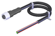
TK2-4131AB024SM8 (Order no. 114819)
Safety switch TK, plug connector M12
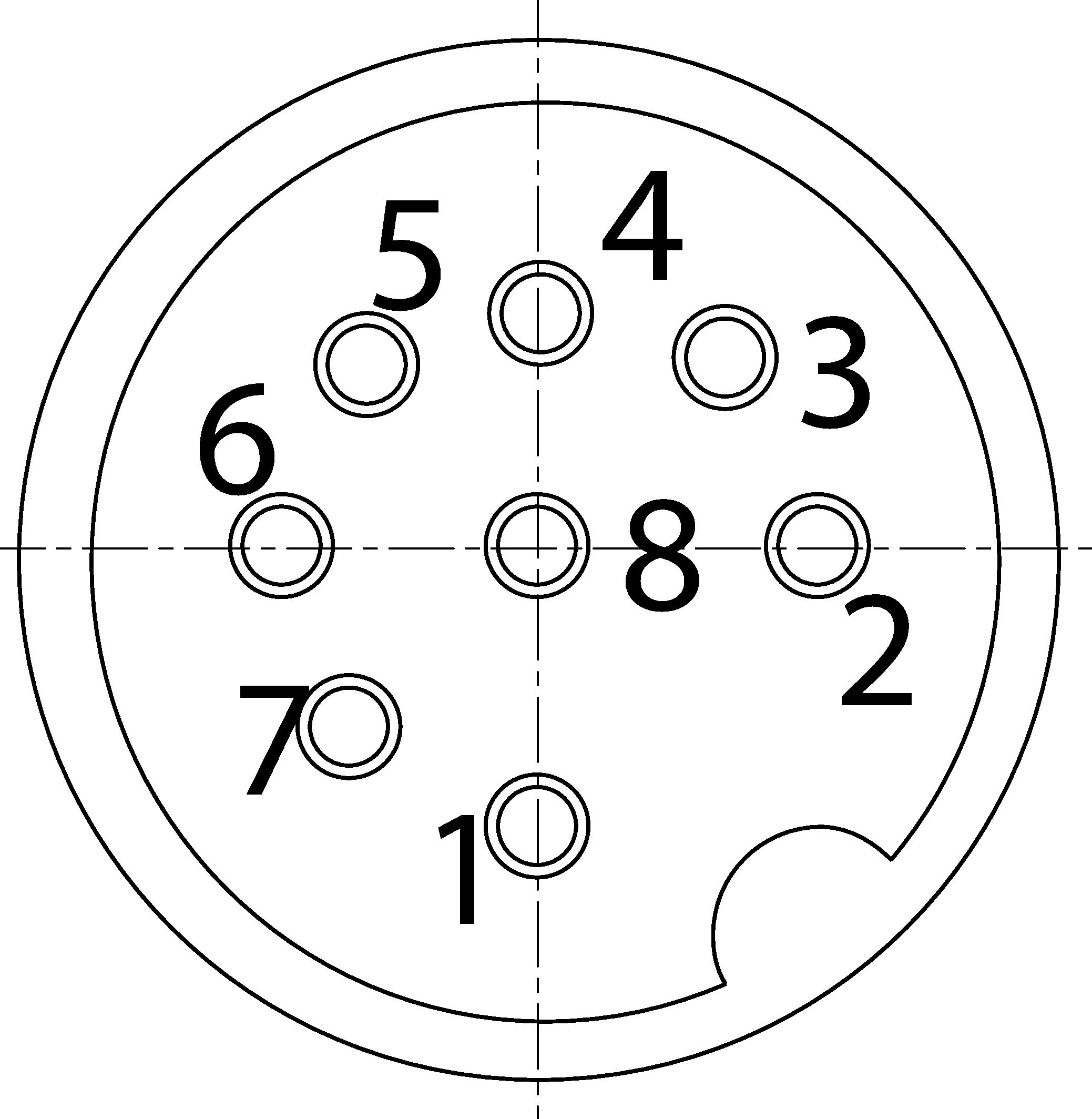
- Plug connector M12, 8-pin
- Auxiliary release on the switch head
- Without prevention of inadvertent locking position (faulty closure protection)
- Guard locking pin right
- Open-circuit current principle

Description
Guard locking principle
Open-circuit current (power on to lock): On a guard with guard locking based on the open-circuit current principle, the guard is locked until the power supply to the guard locking solenoid is interrupted. Unlocking is by spring force. The term electrical guard locking is also used.
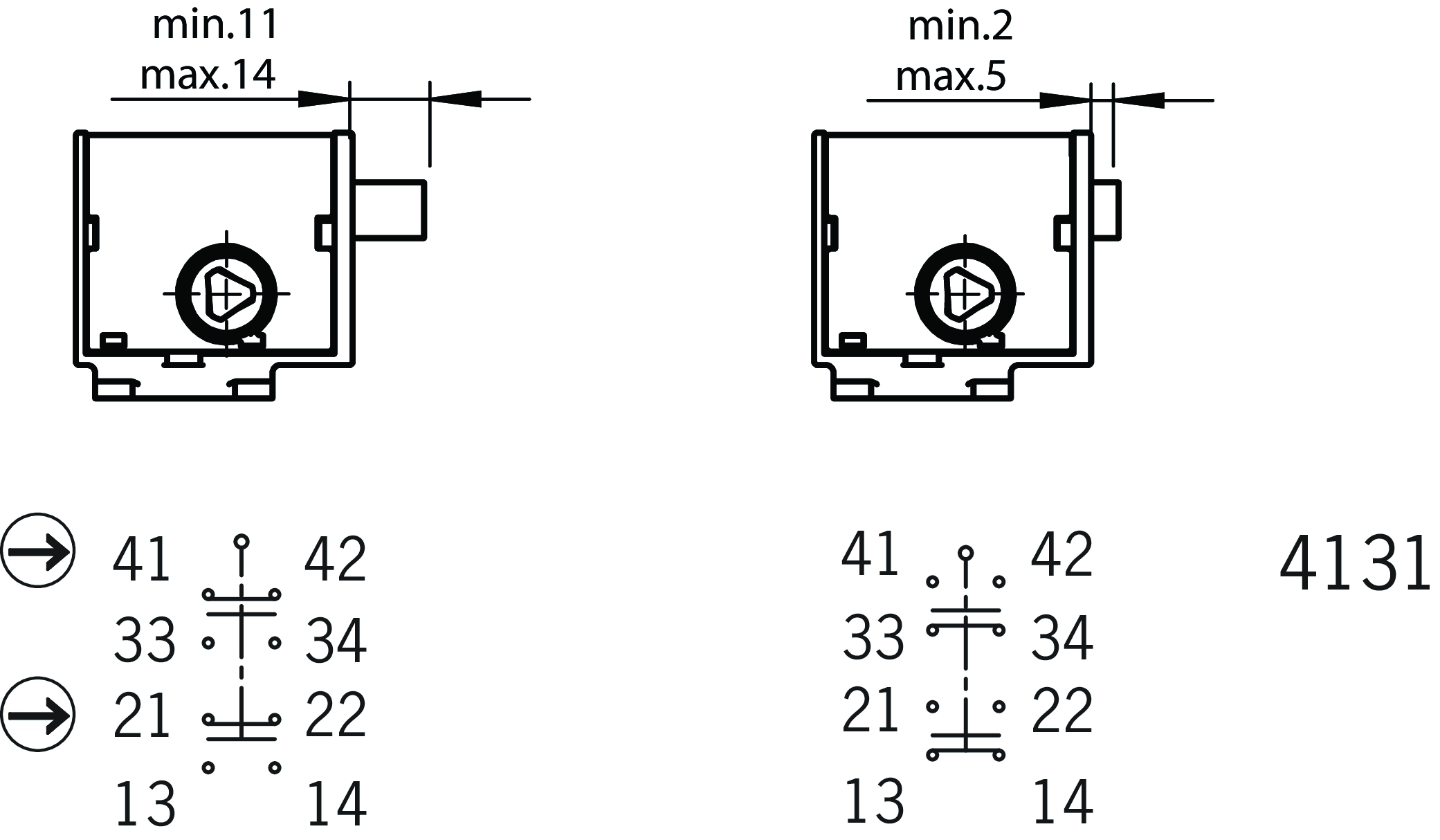
Switching element
4131 | Slow-action switching contact |
Contacts for guard locking: 2 positively driven contacts |
Auxiliary release with triangular wedge
The auxiliary release on the switch head makes it possible to access the machine if there is a malfunction, e.g. a power failure. Unlocking is performed using a tool or a key. The auxiliary release must be protected against misuse (sealing, lacquer).
Contact separation
When actuated, the contacts  are opened. Guard locking is not fully unlocked. The auxiliary release must be sealed to prevent tampering (e.g. with sealing lacquer).
Without prevention of inadvertent locking position (faulty closure protection)
Safety switch TK does not have a prevention of inadvertent locking position (faulty closure protection). This must be implemented separately.
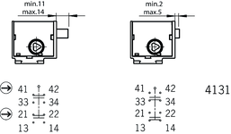

Functional drawings
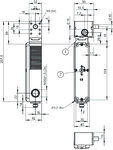
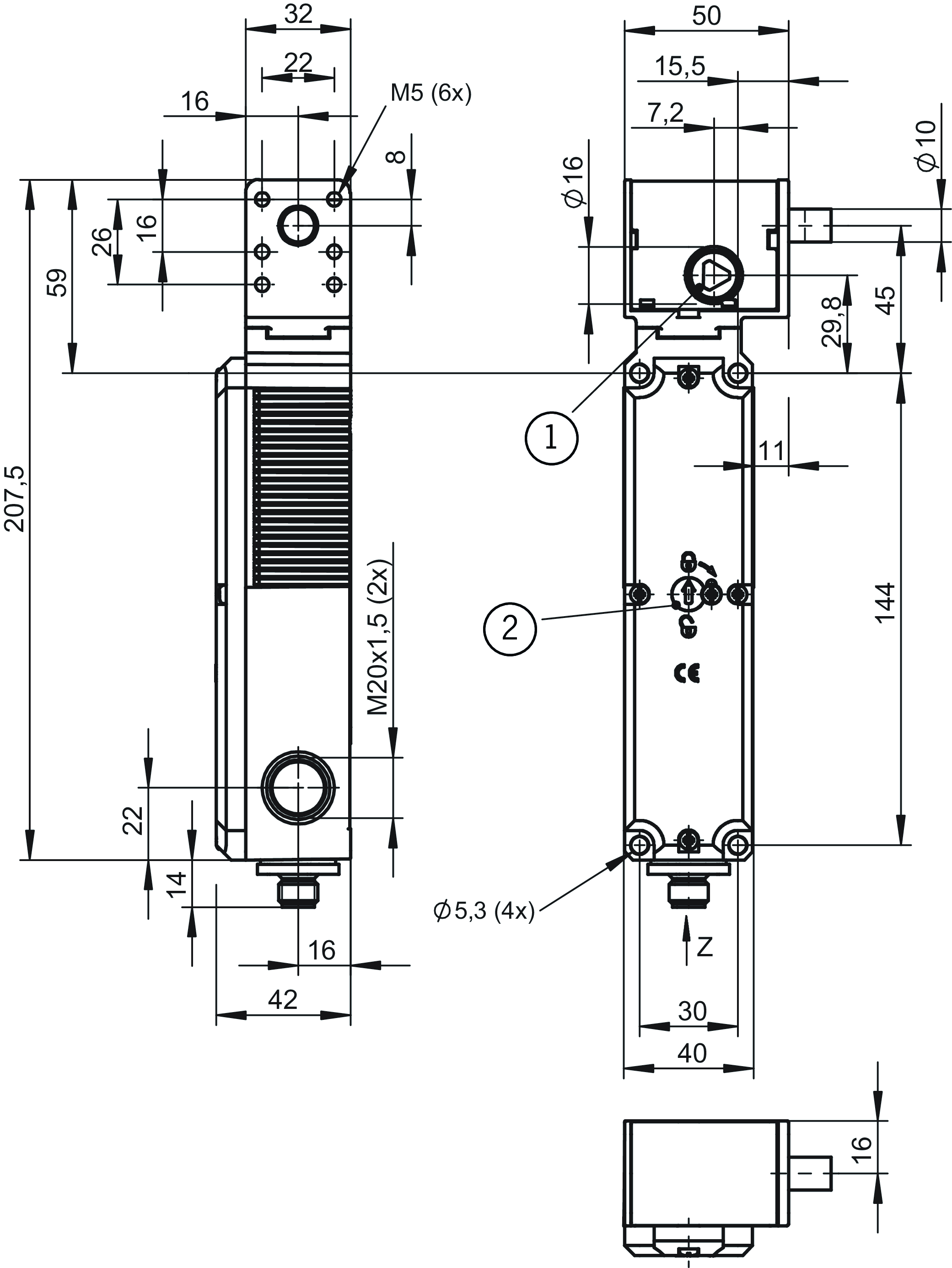
Dimensional drawings
| 1 | Auxiliary release on both sides |
| 2 | Contact separation |
| Plug not aligned |
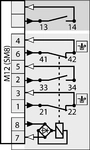
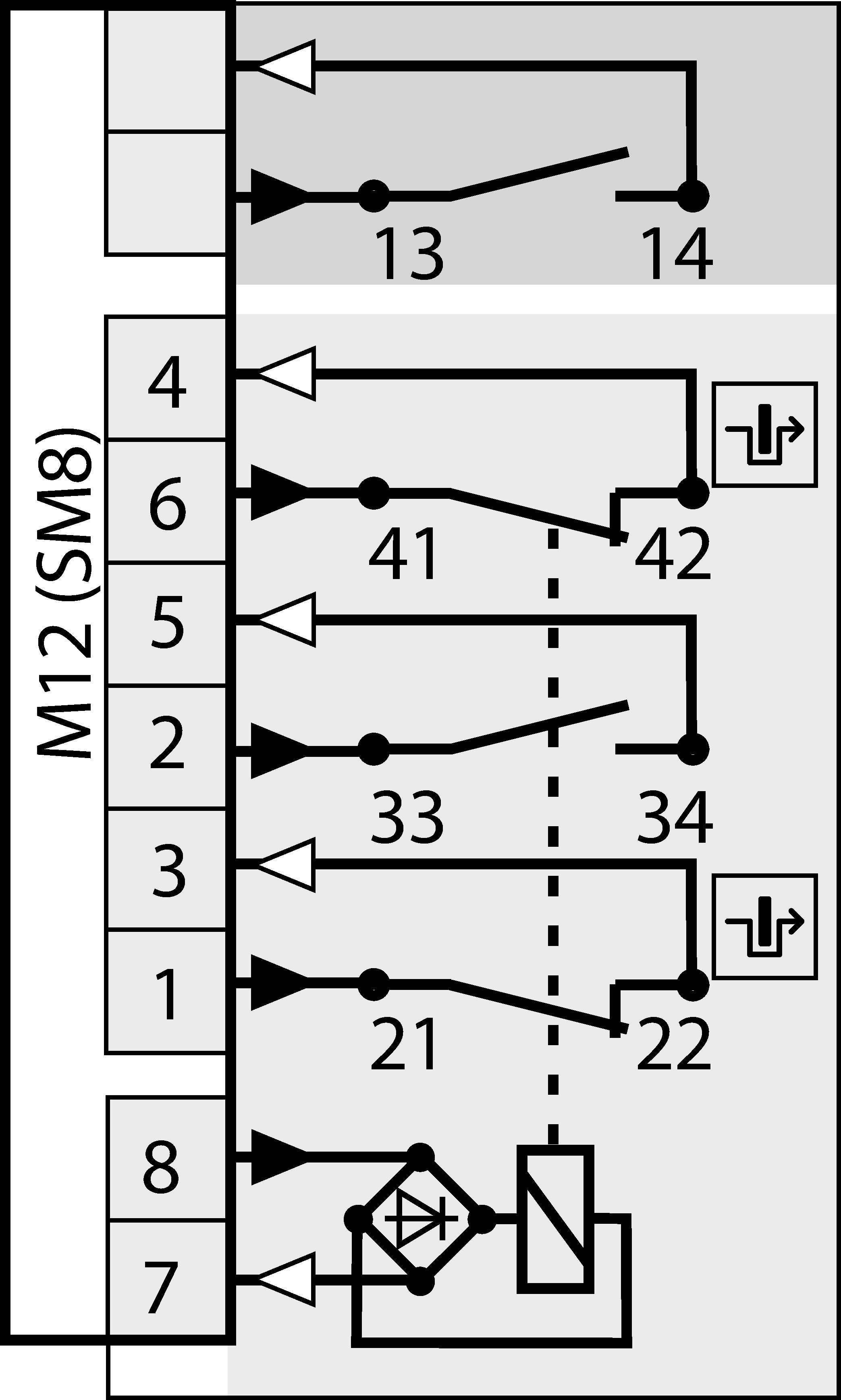
Connection examples
Connection examples
Technical data
Approvals


Electrical connection values
| Fuse | max. 1 A gG |
| Power consumption | 8 W |
| Rated insulation voltage Ui | 30 V |
| Rated impulse voltage Uimp | 1.5 kV |
| Utilization category | |
| AC-15 | 1 A 24 V |
| DC-13 | 1 A 24 V |
| Solenoid operating voltage | |
| AC/DC | 24 V -15% ... +10% |
| Solenoid duty cycle | 100 % |
| Switching voltage | |
| min. at 10 mA | 12 V |
| thermal rated current Ith | 1 A |
Mechanical values and environment
| Approach direction | A |
| Connection type | Plug connector M12 (8-pin) |
| Number of guard lock monitoring NO contacts | 1 |
| Number of guard lock monitoring positively driven contacts | 2 |
| Actuation frequency | max. 1200 1/h |
| Installation orientation | any |
| Mechanical life | 1 x 10⁶ |
| Switching principle | Slow-action switching contact |
| Degree of protection | IP67 |
| Ambient temperature | -20 ... 55 °C |
| Material | |
| Contact | Silver alloy, gold flashed |
| Housing | Reinforced thermoplastic |
| Locking force Fmax | 5000 N |
| Guard locking principle | Open-circuit current principle |
Characteristic values according to EN ISO 13849-1 and EN IEC 62061
| B10D | Mission time | |
|---|---|---|
| Monitoring of guard locking | 2x10⁶ | 20 y |
| Important! Values valid at DC-13 100 mA/24V | ||
Accessories


Downloads
Complete package
Download all important documents with a single click.
Content:
- The operating instructions and any additions to the operating instructions or brief instructions
- Any data sheets to supplement the operating instructions
- The declaration of conformity
Single Documents


Déclaration UE de conformité
Declaración de conformidad UE
EU-Konformitätserklärung
Dichiarazione UE di conformità

Déclaration UE de conformité
Declaración de conformidad UE
EU-Konformitätserklärung
Dichiarazione UE di conformità


Other Documents


Ordering data
| Ordernumber | 114819 |
| Item designation | TK2-4131AB024SM8 |
| Gross weight | 0,62kg |
| Customs tariff number | 85365019000 |
| ECLASS | 27-27-26-03 Safety switch with guard control |