


CEM-M2-C60-PZ-SE-165746 (Order no. 165746)
Choose content
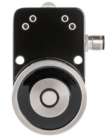
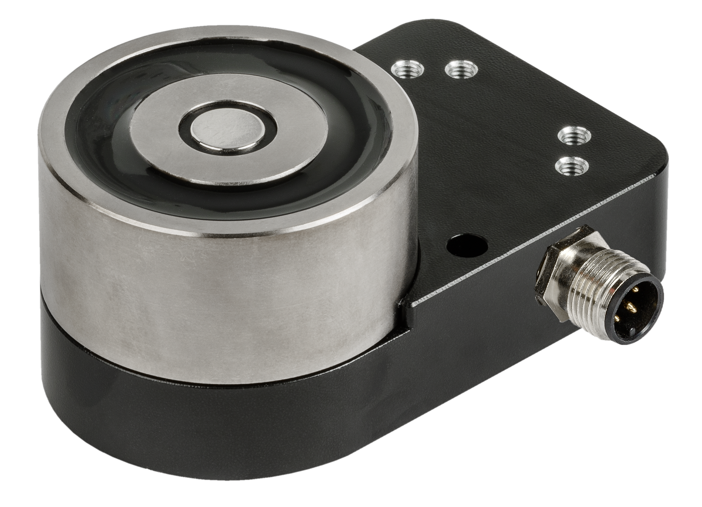
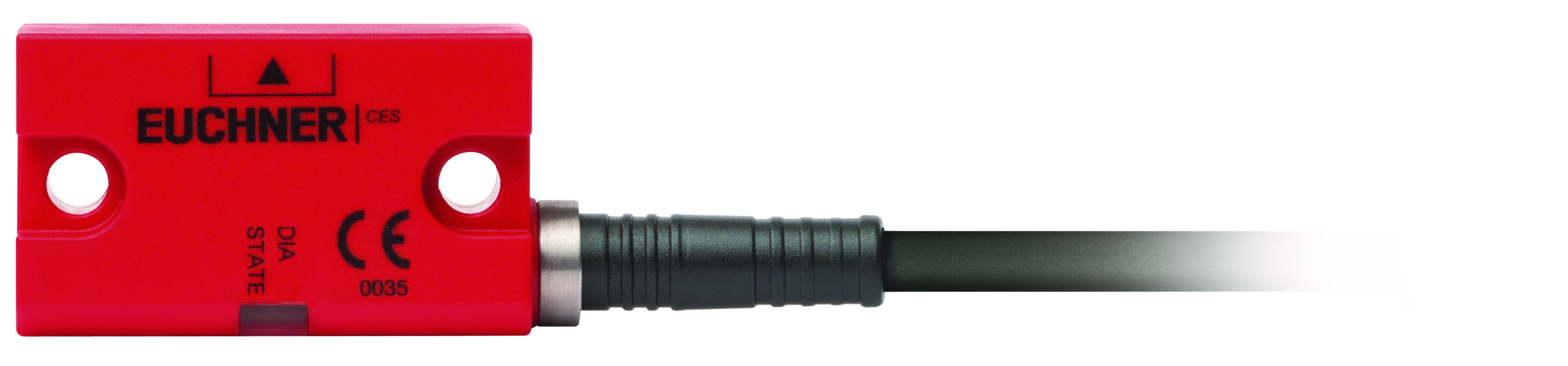
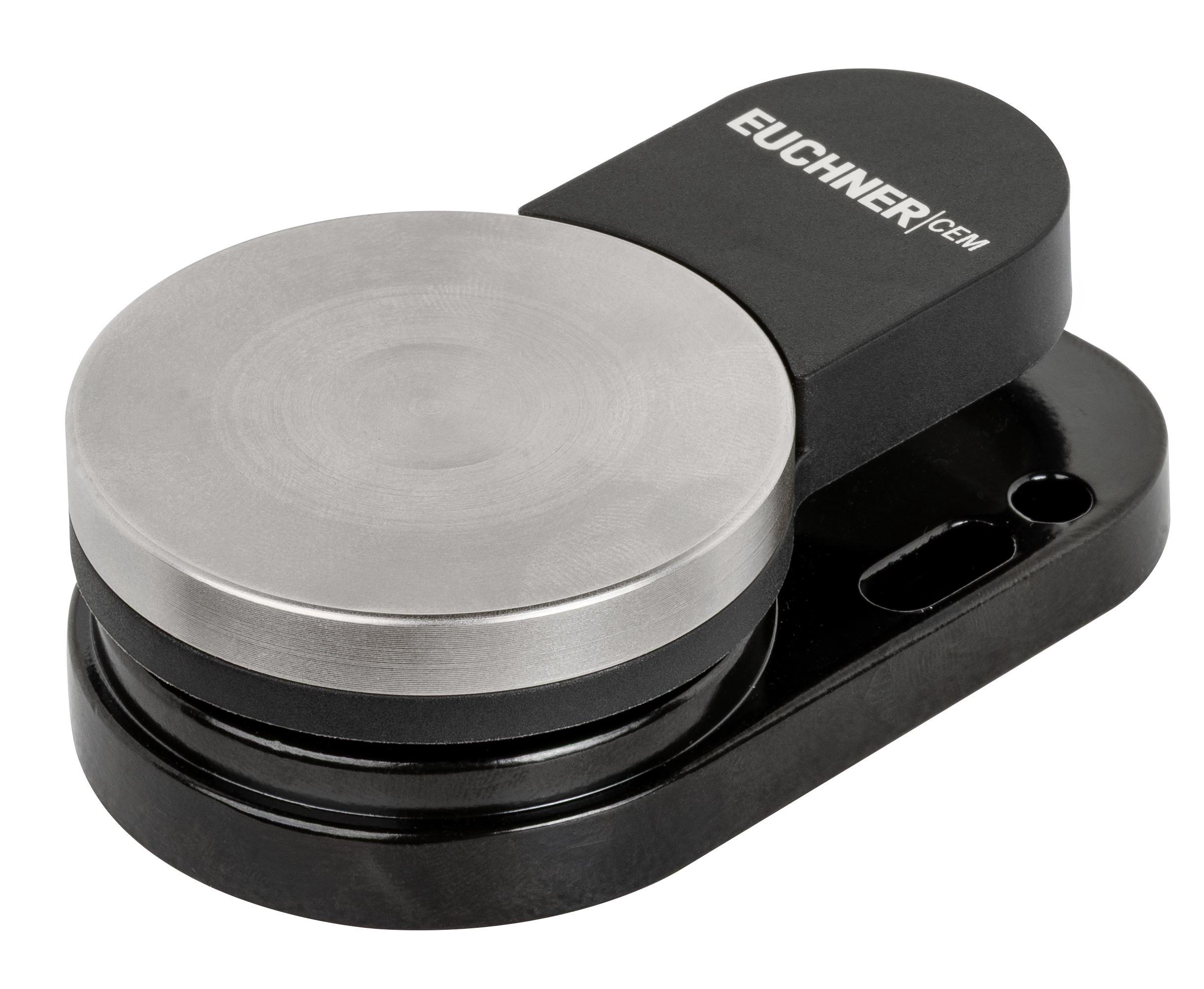
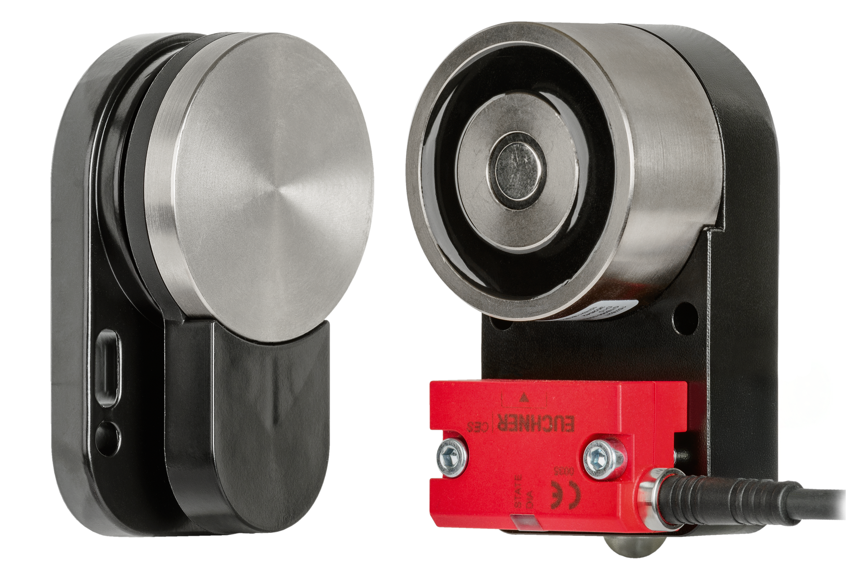
CEM-C60 Electromagnetic Guard Locking for CES-C04 / CES-C07 Safety Switches, M12 Right-Hand Plug Connector(s)
- Plug connector M12, 5-pin
- Plug connector(s) on the right
- Built-in permanent magnet, 30 N adhesive force
Description
Approach direction
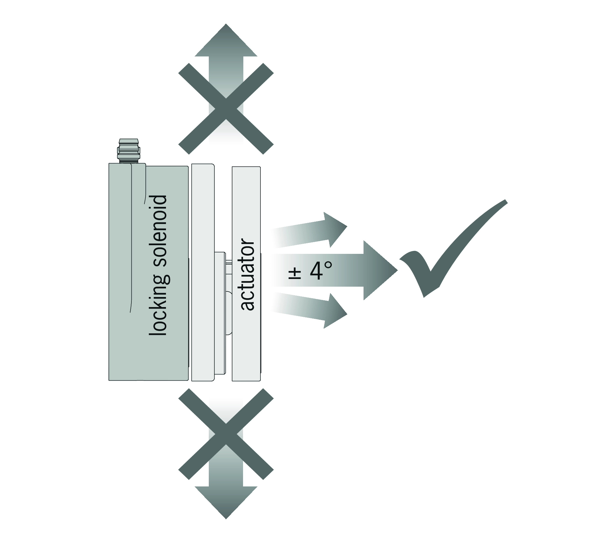
Horizontal
Guard locking principle
Operating current (power to lock): In a safety guard with guard locking based on the open-circuit current principle, the safety guard remains locked until the power supply to the guard locking solenoid is interrupted. This is also referred to as an electrical guard locking.
Combinations
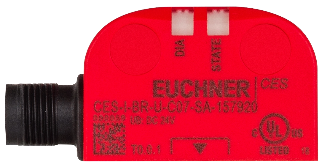
| Guard locking solenoid | Safety switch | Actuator | Application |
|---|---|---|---|
 |  |  |  |
 | |  |
Accessories required
Switches and actuators are not included.
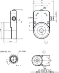
Dimensional drawings
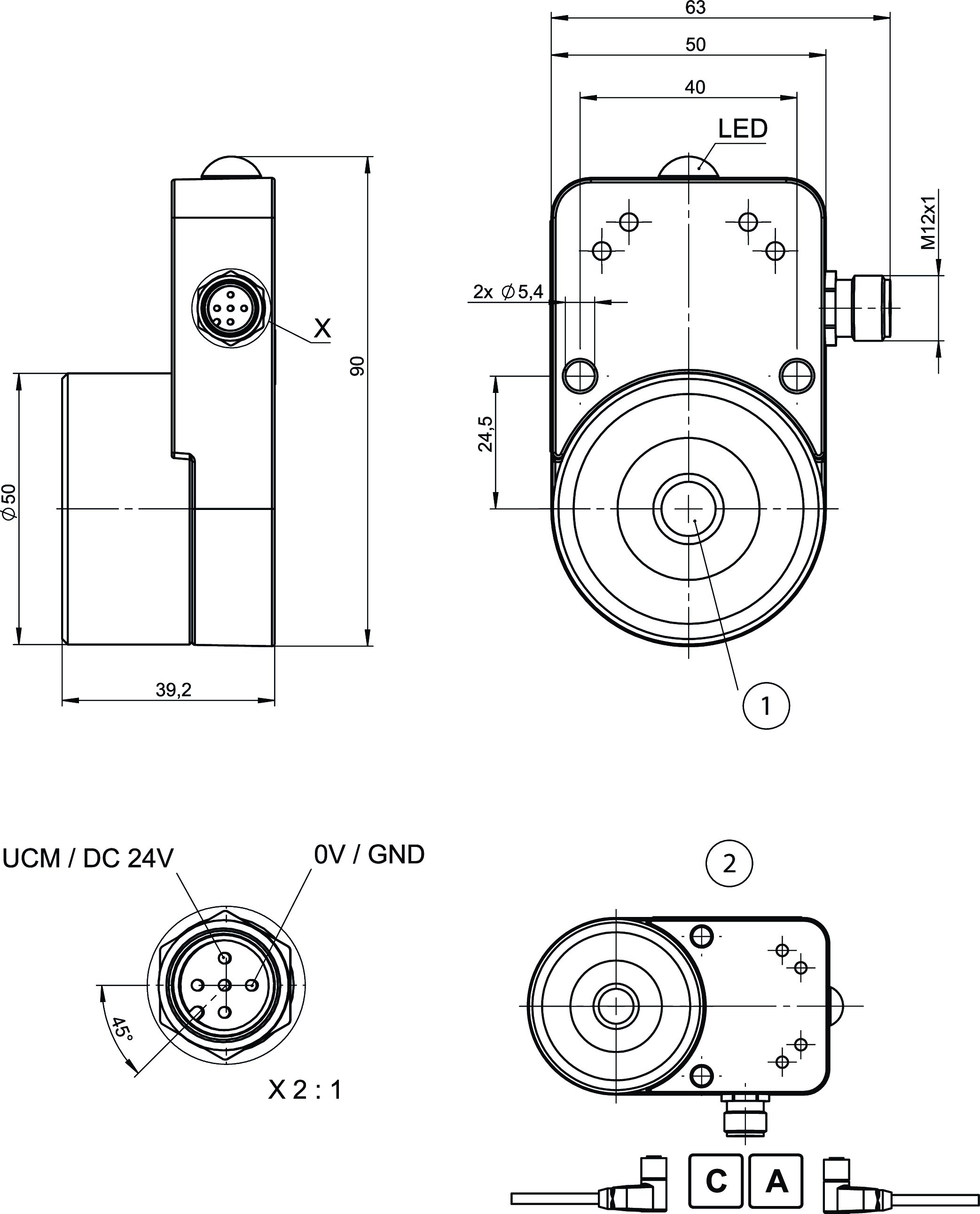
| 1 | Permanent magnet |
| 2 | With the installation orientation shown: cable outlet on left or right |
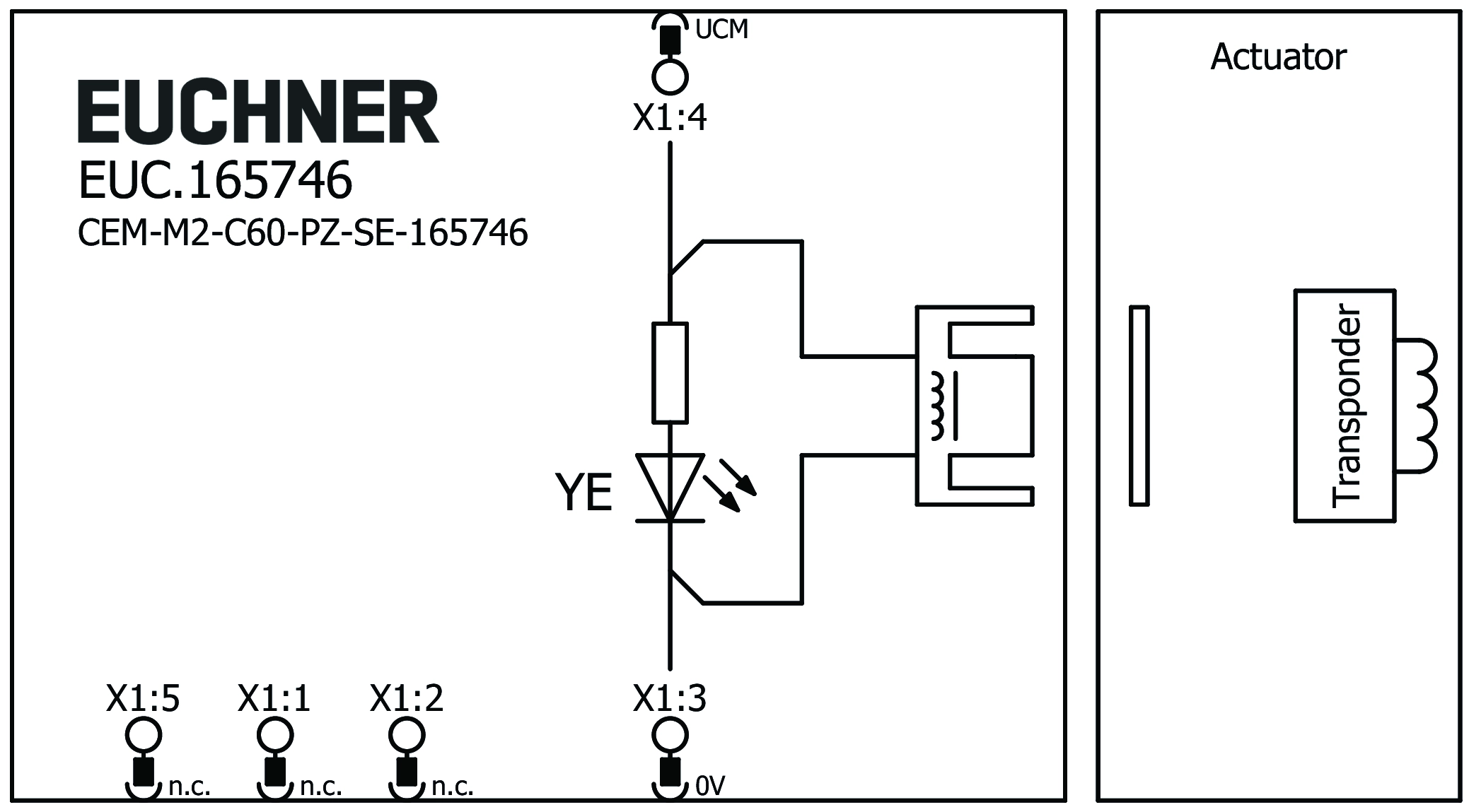
Connection examples
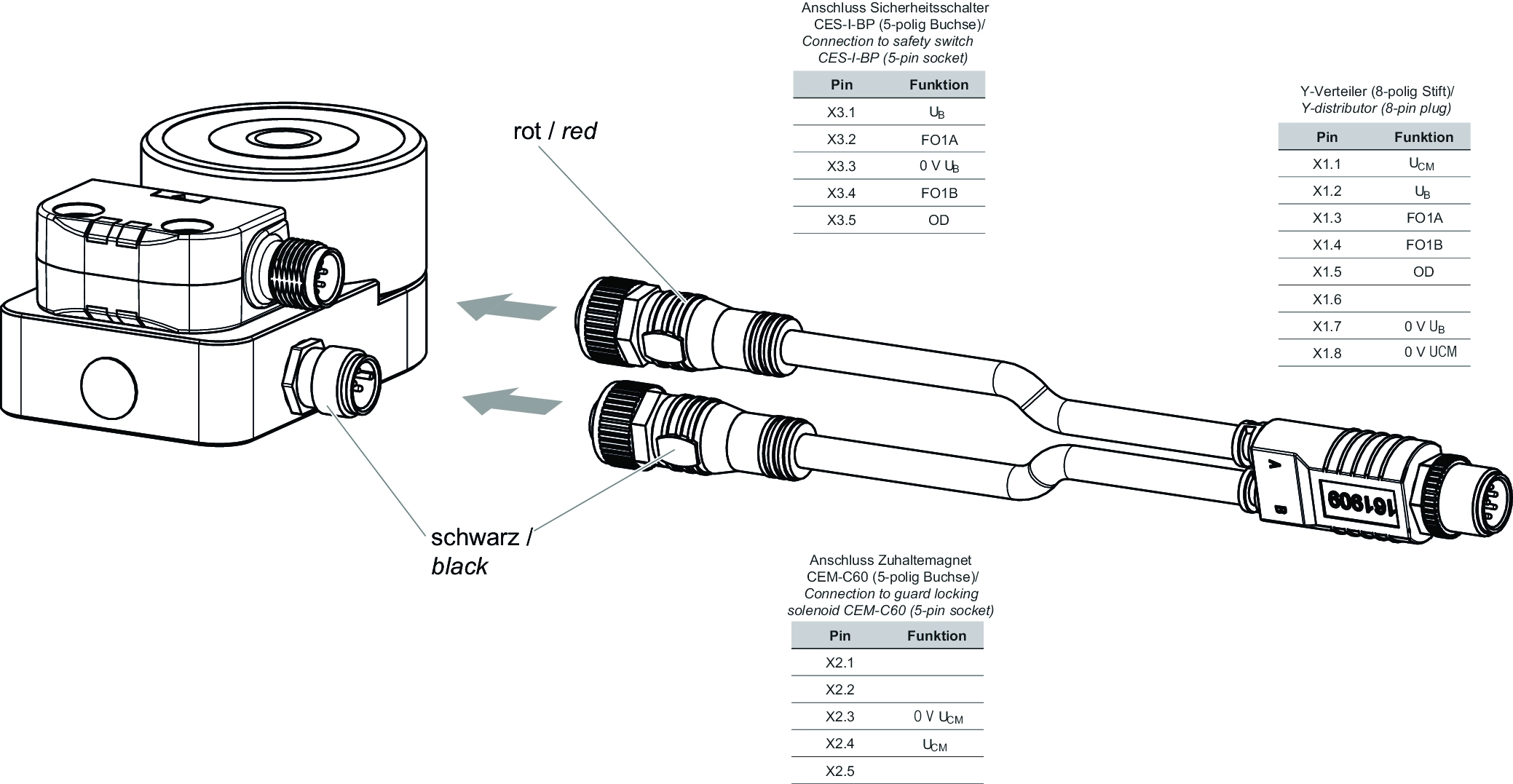
Connection examples
Technical data
Approvals

Workspace
| Center offset | |
| Solenoid | 2.5 mm |
| Transponder detection (typical value at room temperature) | 10 mm |
Electrical connection values
| Power consumption | 2.4 W |
| Operating voltage DC | |
| UCM | 24 V DC -15% ... +10% |
| Solenoid duty cycle | 100 % |
| Current consumption | 100 mA |
Mechanical values and environment
| Connection type | M12, 5-pin – RIGHT |
| Installation orientation | any |
| Adhesive force | |
| by permanent magnet | 30 N 0 ... +15 |
| Storage temperature | -25 ... 70 °C |
| Mechanical life | |
| in case of use as door stop, and 1 Joule impact energy | 1 x 10⁶ |
| Degree of protection | IP65/IP67 |
| Ambient temperature | -25 ... 50 °C |
| Material | |
| Housing | Aluminum |
| Solenoid | Steel, nickel plated |
| Locking force F | |
| (not monitored, in axial direction) at UCM=24 V | 650 N |
| Guard locking principle | Open-circuit current principle |
In combination with safety switch CES-I-BP-M-C07-SB-160076, CES-I-BP-U-C07-SB-160080, CES-I-BR-U-C07-SA-157920, CES-I-BP-M-C07-SI-162813, CES-I-BP-U-C07-SI-162815, CES-I-BR-M-C07-SA-156233, CES-I-BR-S-C07-SA-165914
| Secured switch-off distance sar | 17 mm |
| Secured switching distance sao | |
| with center offset m=0 | min. 2 mm |
In combination with safety switch CES-I-AP-U-C04-USI-115150, CES-I-AP-U-C04-SK-115324, CES-I-AP-U-C04-USB-116502, CES-I-AP-U-C04-U05-116503, CES-I-AP-U-C04-U10-116504, CES-I-AP-U-C04-U20-116505, CES-I-AP-M-C04-USI-117323, CES-I-AP-M-C04-USB-117324, CES-I-AP-M-C04-SK-117325, CES-I-AP-M-C04-U05-117328, CES-I-AP-M-C04-U10-117329, CES-I-AP-M-C04-U20-117330, CES-I-AR-U-C04-SG-119469, CES-I-AR-U-C04-U05-119470, CES-I-AR-U-C04-U10-119471, CES-I-AR-U-C04-U20-119472, CES-I-AR-U-C04-USA-119473, CES-I-AR-M-C04-SG-119474, CES-I-AR-M-C04-U05-119475, CES-I-AR-M-C04-U10-119476, CES-I-AR-M-C04-U20-119477, CES-I-AR-M-C04-USA-119479, CES-I-AP-M-C04-USI-160832, CES-I-AR-F-C04-SG-161679, CES-I-AP-M-C04-USI-162592
| Secured switch-off distance sar | 40 mm |
| Secured switching distance sao | |
| with center offset m=0 | min. 5 mm |
Accessories

Connection material

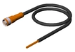
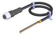
M12 extension PUR, 5-pin, plug connectors at both ends, 10 m
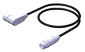
115565
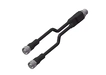
C-M12F05-05X025PU10,0-M12M05-115565
C-M12F05-05X025PU10,0-M12M05-115565
- M12 female plug, 5-pin (angled) to M12 plug connector (straight)
- plug connectors at both ends
- PUR cable
- Cable length 10 m
- with cable exit A (right)
115566
C-M12F05-05X025PU10,0-M12M05-115566
C-M12F05-05X025PU10,0-M12M05-115566
- M12 female plug, 5-pin (angled) to M12 plug connector (straight)
- plug connectors at both ends
- PUR cable
- Cable length 10 m
- with cable exit C (left)
Downloads
Complete package
Download all important documents with a single click.
Content:
- The operating instructions and any additions to the operating instructions or brief instructions
- Any data sheets to supplement the operating instructions
- The declaration of conformity
Download Complete Package (ZIP, 0,9 MB)
Single Documents
Declarations of conformity
EU-Konformitätserklärung

Doc. no.
Version
Language
Size
EU-Konformitätserklärung
Doc. no.
Version
Language
Size
0,1 MB
UKCA-Konformitätserklärung

Doc. no.
Version
Language
Size
UKCA-Konformitätserklärung
Doc. no.
EDC20001469
Version
01
Language
Size
0,1 MB


Other Documents
Approvals and certificates
WEEE

Doc. no.
Version
Language
Size
WEEE
Doc. no.
ECO20001806
Version
01
Language
Size
0,1 MB
c UL us

Doc. no.
Version
Language
Size
c UL us
Doc. no.
Version
Language
Size
0,3 MB
Sales documents


Transponder-coded safety systems - CEM with guard locking for process protection


Doc. no.
Version
Language
Size
Transponder-coded safety systems - CEM with guard locking for process protection
Doc. no.
136679
Version
03-08/20
Language
Size
4,2 MB
Systèmes de sécurité à codage par transpondeur CEM avec verrouillage pour la protection du process
Doc. no.
136680
Version
03-08/20
Language
Size
3,8 MB
Sistemas de seguridad codificados por transponder CEM con bloqueo para la protección de procesos
Doc. no.
136681
Version
03-08/20
Language
Size
2,1 MB
Transpondercodierte Sicherheitssysteme - CEM mit Zuhaltung für den Prozessschutz
Doc. no.
129544
Version
03-08/20
Language
Size
4,2 MB
Sistemi di sicurezza con codifica a transponder CEM con meccanismo di ritenuta per la protezione del processo
Doc. no.
168668
Version
03-08/20
Language
Size
9,0 MB

ePlan macros
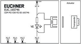
EUC.165746
Doc. no.
Version
Language
Size
EUC.165746
Doc. no.
Version
Language
Size
0,2 MB

Ordering data
| Ordernumber | 165746 |
| Item designation | CEM-M2-C60-PZ-SE-165746 |
| Gross weight | 0,505kg |
| Customs tariff number | 85389099 |
| ECLASS 11.0 | 27-27-24-05 Safety-related transponder switch with guardlocking |