


CES-I-AS2A-U-C04-SC-120547 (Order no. 120547)
CES-.-AS-C04 ASi safety switch, RFID, M8 plug connector(s)
- AS-Interface
- Unicode
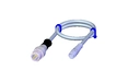
- Plug connector M8, 3-pin
- LED indicator
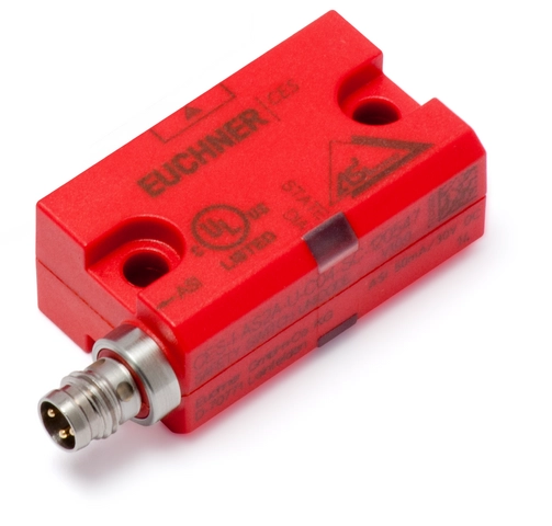
Description
Approach direction and installation position
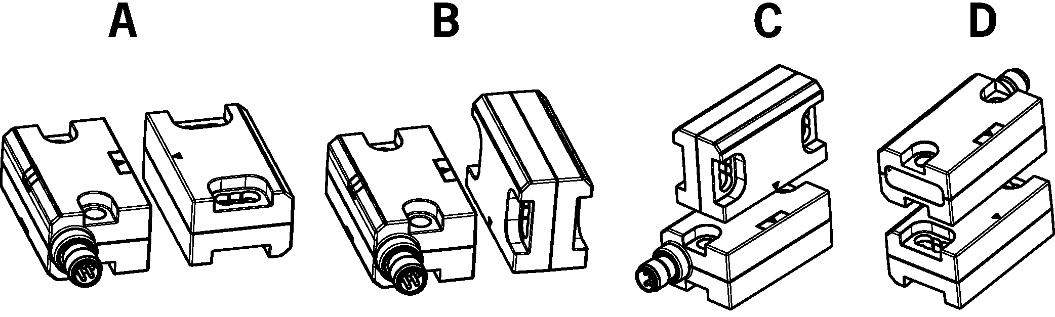
Permissible installation position
Typical operating distance
(only in combination with actuator CES-A-BBN-C04)
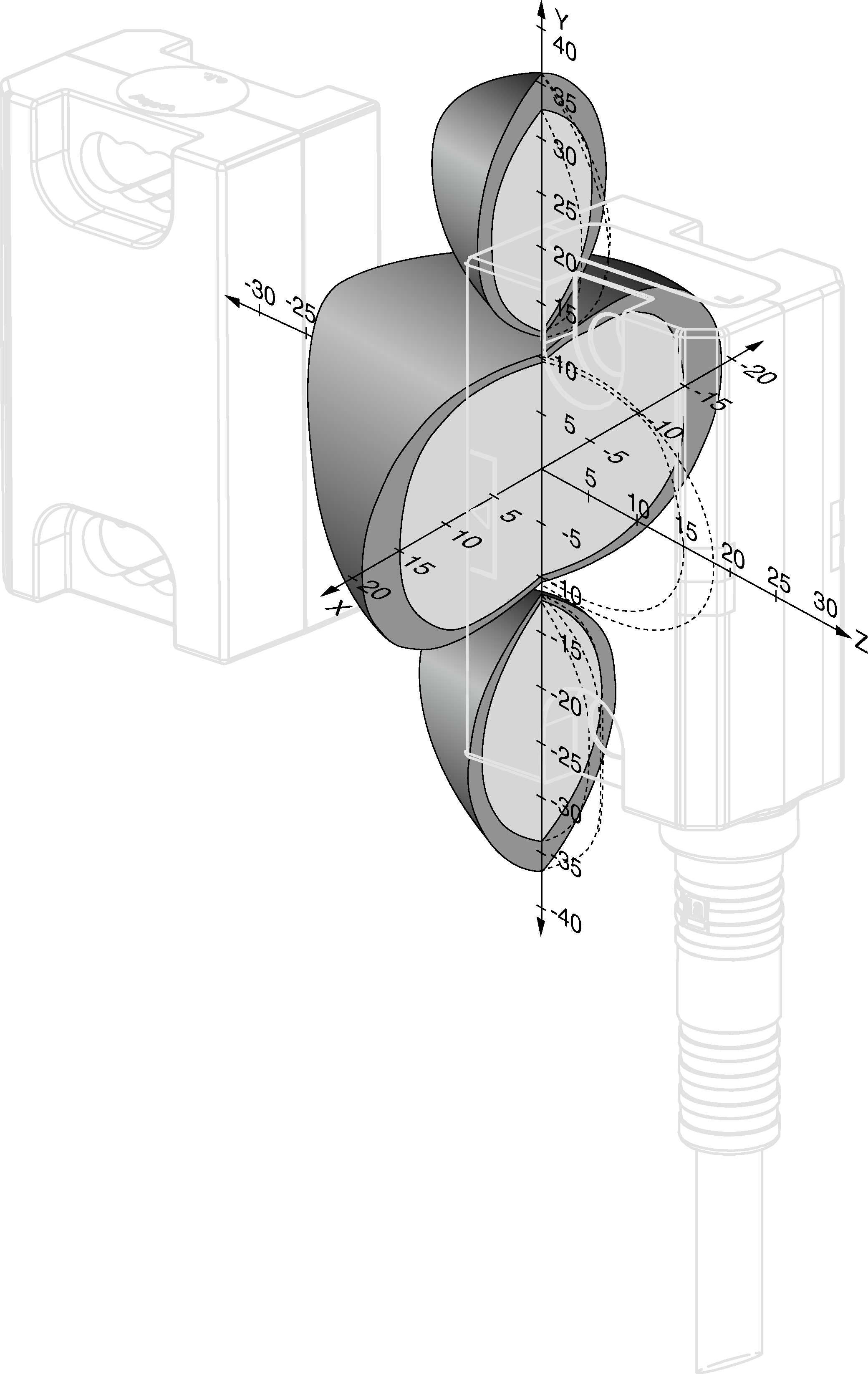
For a side approach direction for the actuator and safety switch, a minimum distance of s = 6 mm must be maintained so that the actuating range of the side lobes is not entered.
Attention:
The actuating range may vary depending on the actuator, substrate material and installation situation. You can find additional actuating ranges in the operating instructions.
Unicode evaluation
Each actuator is highly coded (unicode). The switch detects only taught-in actuators. Additional actuators can be taught-in.
Only the last actuator taught-in is detected.
Safety characteristics
Due to two redundantly designed safety outputs (semiconductor outputs) with internal monitoring, the device is suitable for:
- Category 4 /PL e according to EN 13849-1
- SIL 3 according to EN IEC 62061 Table 4
The OSSD outputs used check their function for short circuits using test pulses.
AS-Interface inputs
D0, D1, D2, D3 | Monitoring of the guard position |
LED indicator
- The dual-LED ASi indicator on the M8 plug connector displays the status of the ASi bus.
- The STATE LED indicates the state of the switch.
- The DIA LED indicates whether a fault has been detected in the switch.
Plug connector aligned C04
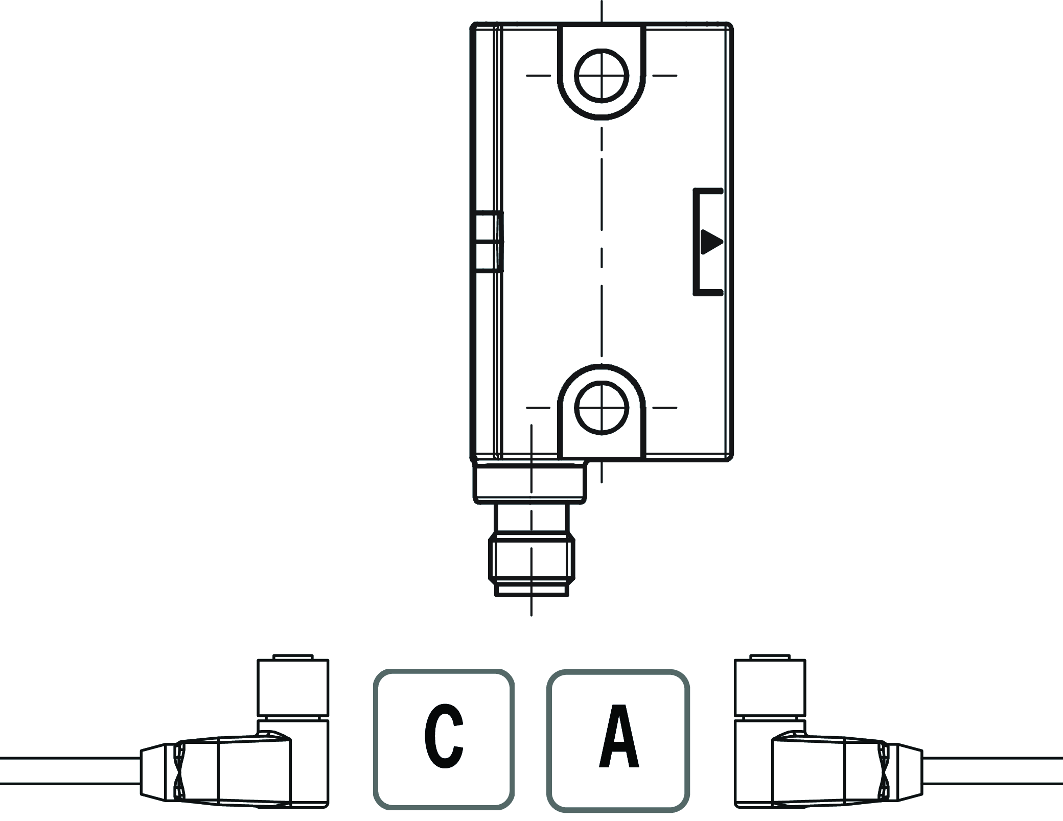
The following applies to the device installation position shown: cable outlet C (left), cable outlet A (right).
Accessories required
Actuator is not included.
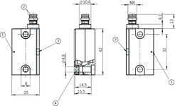
Dimensional drawings
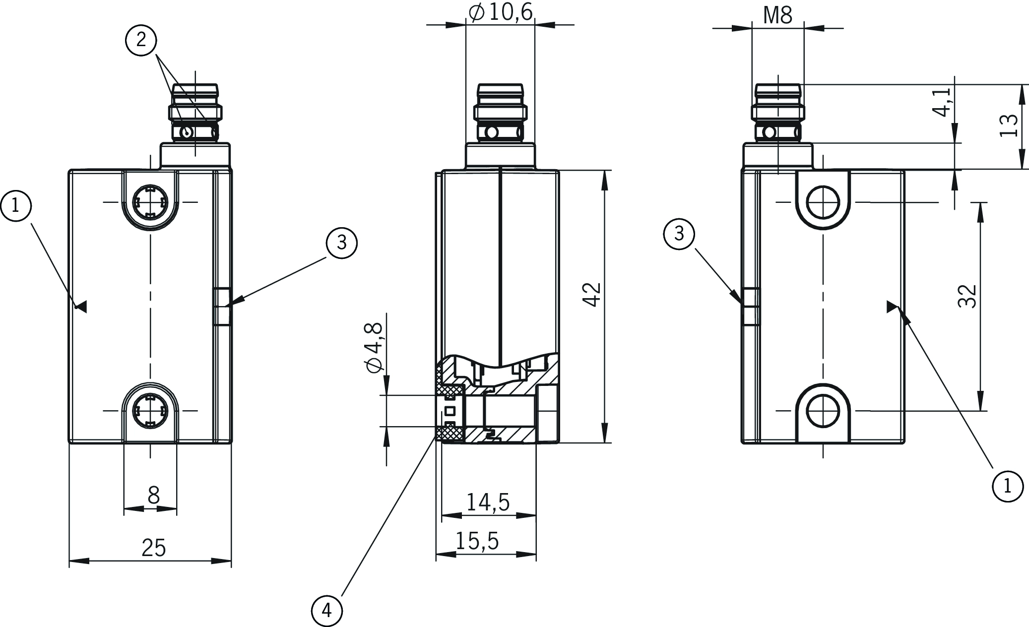
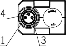
| 1 | Active face |
| 2 | ASi green/red |
| 3 | LED status indication |
| 4 | Rubber support |
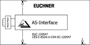
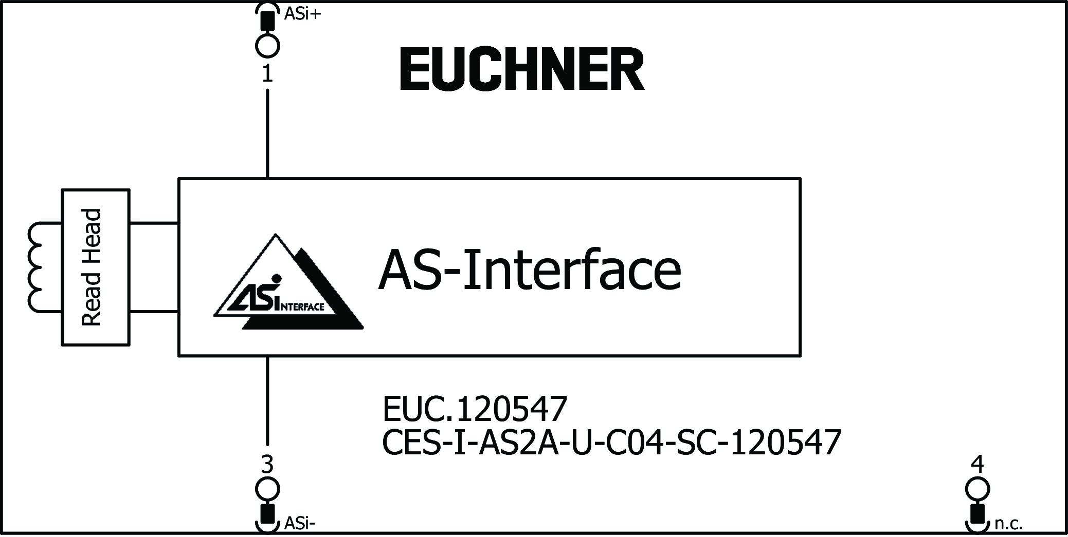
Connection examples
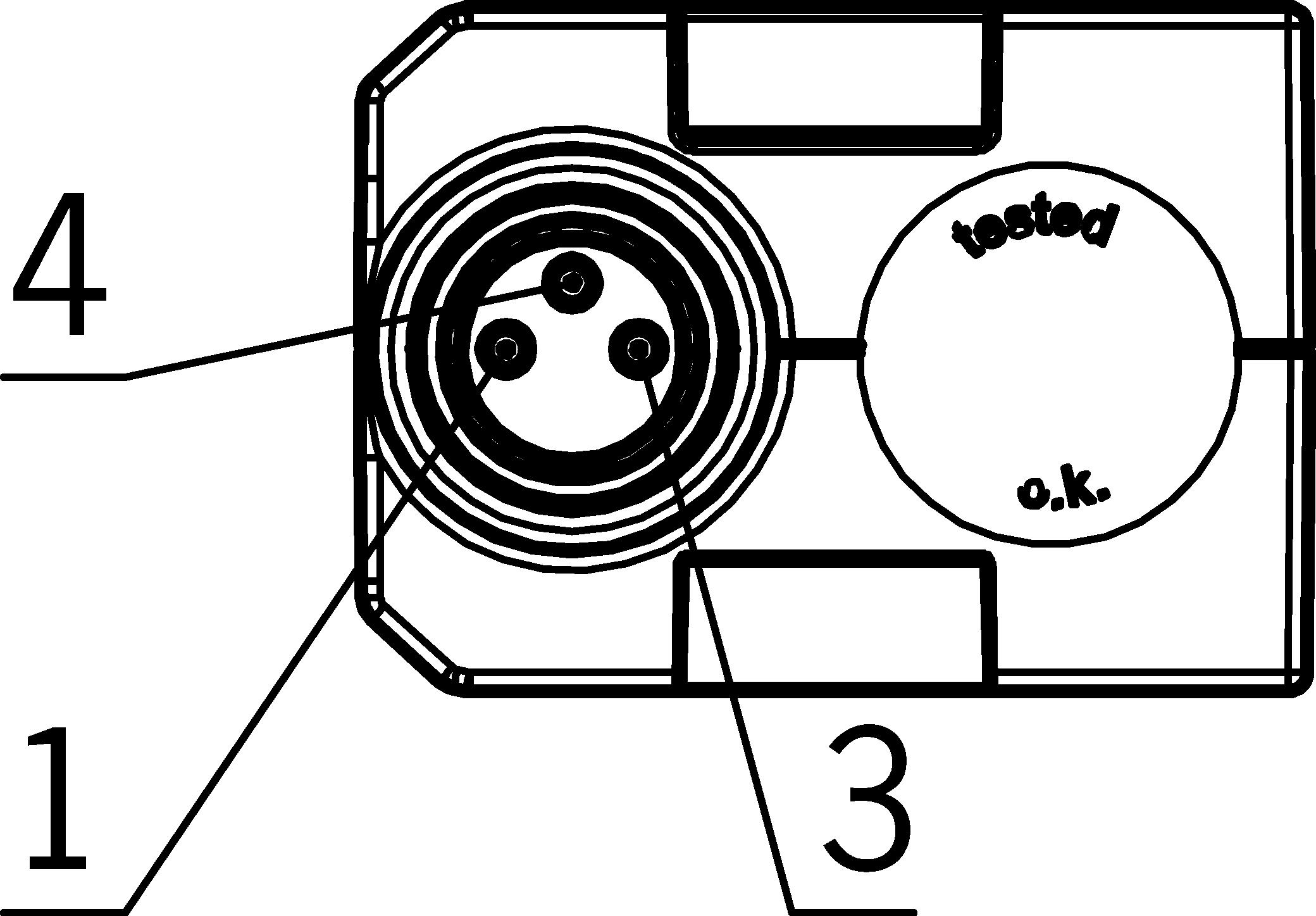
| PIN 1 | AS-i + |
| PIN 3 | AS-i - |
| PIN 4 | n.c. |
Connection examples
Technical data
Approvals


Workspace
| Repeat accuracy R | |
| according to EN 60947-5-2 | 10 % |
Electrical connection values
| ASI operating current | max. 50 mA |
| AS-Interface protocol | ASi-3 |
| ASI data in | D0 - D3 = door position |
| AS-Interface slave type | ID-Code: B, EA-Code: 0 |
| ASI voltage | 19 ... 30 ... 31.6 V |
| Rated insulation voltage Ui | 75 V |
| Rated impulse voltage Uimp | 1.5 kV |
| Turn-on time | |
| Safety outputs | max. 300 ms |
| Risk time according to EN 60947-5-3 | max. 260 ms |
| Safety class | III |
| Degree of contamination (external, according to EN 60947-1) | 3 |
Mechanical values and environment
| Dimensions | 42 x 25 x 18 |
| Connection type | M8 plug connector, 3-pin |
| Tightening torque | |
| Plug connector | max. 0.3 Nm |
| Fixing screws | max. 0.8 Nm |
| Installation orientation | any |
| Switching frequency | max. 1 Hz |
| Storage temperature | -25 ... 70 °C |
| Mounting distance | |
| between switches | min. 80 mm |
| Shock and vibration resistance | Acc. to EN IEC 60947-5-3 |
| Degree of protection | IP67 |
| Ambient temperature | -25 ... 65 °C |
| Material | |
| Housing | Plastic, PBT |
| Rubber support | NBR 80 ±5 Shore |
Characteristic values according to EN ISO 13849-1 and EN IEC 62061
| PL | Maximum SIL | PFHD | Category | Mission time | |
|---|---|---|---|---|---|
| Monitoring of the guard position | PL e | - | 4.5x10⁻⁹ | 4 | 20 y |
Miscellaneous
| Notices for UL approval | Operation only with UL Class 2 power supply or equivalent measures |
In combination with actuator CES-A-BDN-06-104730, CES-A-BBN-C04-115271
| Secured switch-off distance sar | |
| in x/z direction | 40 mm |
| in y direction | 60 mm |
| Switching hysteresis | 1 ... 2 mm |
In combination with actuator CES-A-BDN-06-104730
| Switch-on distance | |
| Approach direction A or B (front side) | 19 mm |
| Approach direction C or D (broad side) | 15 mm |
| Secured switching distance sao | |
| Approach direction C or D (broad side) | min. 10 mm |
| Approach direction A or B (front side) | min. 14 mm |
In combination with actuator CES-A-BBN-C04-115271
| Switch-on distance | |
| Approach direction A or B (front side) | 15 mm |
| Approach direction C or D (broad side) | 11 mm |
| Secured switching distance sao | |
| Approach direction C or D (broad side) | 6 mm |
| Approach direction A or B (front side) | 10 mm |
In combination with actuator CES-A-BBN-161502
| Switch-on distance | |
| Installation position A + B | 30 mm |
| Installation position C + D | 25 mm |
| Secured switch-off distance sar | |
| in y direction / installation position C + D | 72 mm |
| in y direction / installation position A + B | 77 mm |
| in x/z direction / installation position A + B | 69 mm |
| in x-/z direction / installation position C + D | 63 mm |
| Secured switching distance sao | |
| Installation position A + B | 15 mm |
| Installation position C + D | 10 mm |
| Switching hysteresis | min. 1 mm |
Accessories
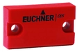
CES-A-BBN-161502
- Cube-shaped design 42 x 25 mm, height 12 mm
- Transponder with large actuating range
- Mounting compatible with actuators: CES-A-BBA-071840, CES-BBN-106600, CES-A-BBN-C04-115271
- Two safety screws M4x14 included
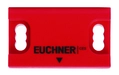
CES-A-BBN-C04-115271
- Cube-shaped design 42 x 25 mm
- Two safety screws M4x20 and rubber support included


Downloads
Complete package
Download all important documents with a single click.
Content:
- The operating instructions and any additions to the operating instructions or brief instructions
- Any data sheets to supplement the operating instructions
- The declaration of conformity
Single Documents


Other Documents


ePlan macros

Ordering data
| Ordernumber | 120547 |
| Item designation | CES-I-AS2A-U-C04-SC-120547 |
| Gross weight | 0,06kg |
| Customs tariff number | 85365019000 |
| ECLASS 11.0 | 27-27-24-03 Safety-related transponder switch |