Rope pull switch RPS
Description
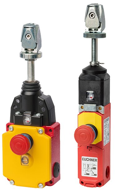
Rope pull switches RPS are emergency stop devices for protecting large, expansive machine or installation areas that cannot be protected by an enclosing housing or cover. Areas of an installation or machine can be shut down immediately from any point in the working area in the event of danger.- EMERGENCY STOP device with detent mechanism according to EN ISO 13850
- Indication of correct rope tension
- Switching elements with 4 switching contacts
Task of rope pull switches
In contrast to switches with EMERGENCY STOP pushbuttons, rope pull switches have a significantly larger triggering range, as actuation is possible over the entire length of the rope and is not limited to the small area within immediate reach of the switch. Rope pull switches are used wherever extensive danger areas need to be secured.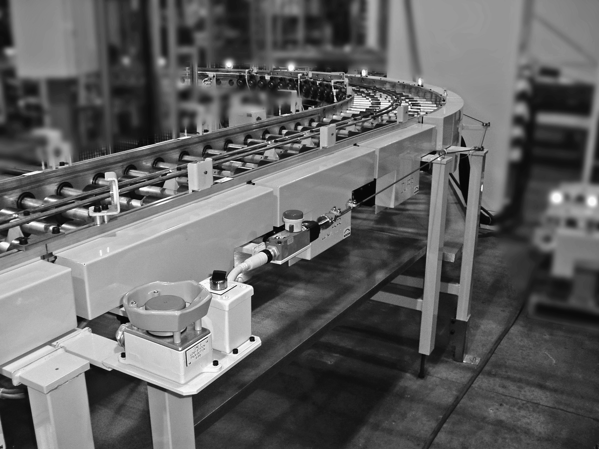 The advantage of rope pull switches is that plant or machine areas can be shut down immediately from any point in the work area in the event of danger - without the need to install individual EMERGENCY STOP devices at short intervals.
Function and technology of rope pull switches
EN 60947-5-5 - 6 (requirements for EMERGENCY STOP pushbuttons and rope pull switches) defines precise guidelines for the functionality of rope pull switches. For example, the reset of the latching device (EMERGENCY STOP button) must be carried out either by turning a key, turning the pushbutton in the specified direction or by a pulling movement. Rope pull switches are usually activated by pulling on a plastic-coated steel cable.In addition, EUCHNER's rope pull switches have an EMERGENCY STOP latching switch on the housing that fulfills the same function. When activated, the safety contacts are actuated and a stop signal is generated, which switches the machine off immediately. Similarly, a break or unhooking of the rope must activate an EMERGENCY STOP signal. This means that a defect in the safety system is detected immediately and the safety function is warranted at all times.
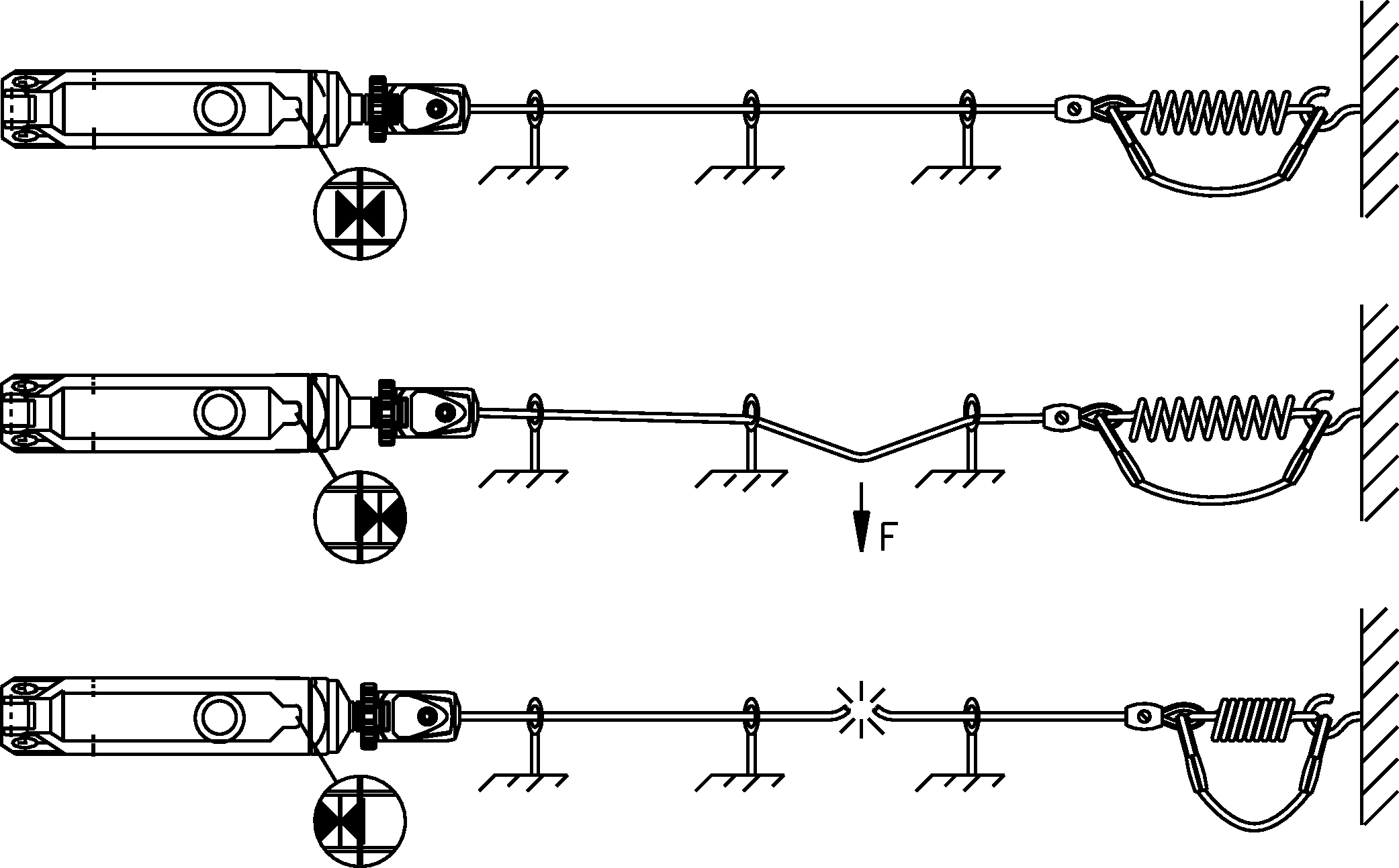 For this function, the rope pull switches have a center position and two switch-off positions. During normal machine mode, the switch is in the center position. If the rope is pulled or breaks, the switch changes to one of the switch-off positions and stops the machine. The EUCHNER rope pull switches are also equipped with a window to display the rope position.
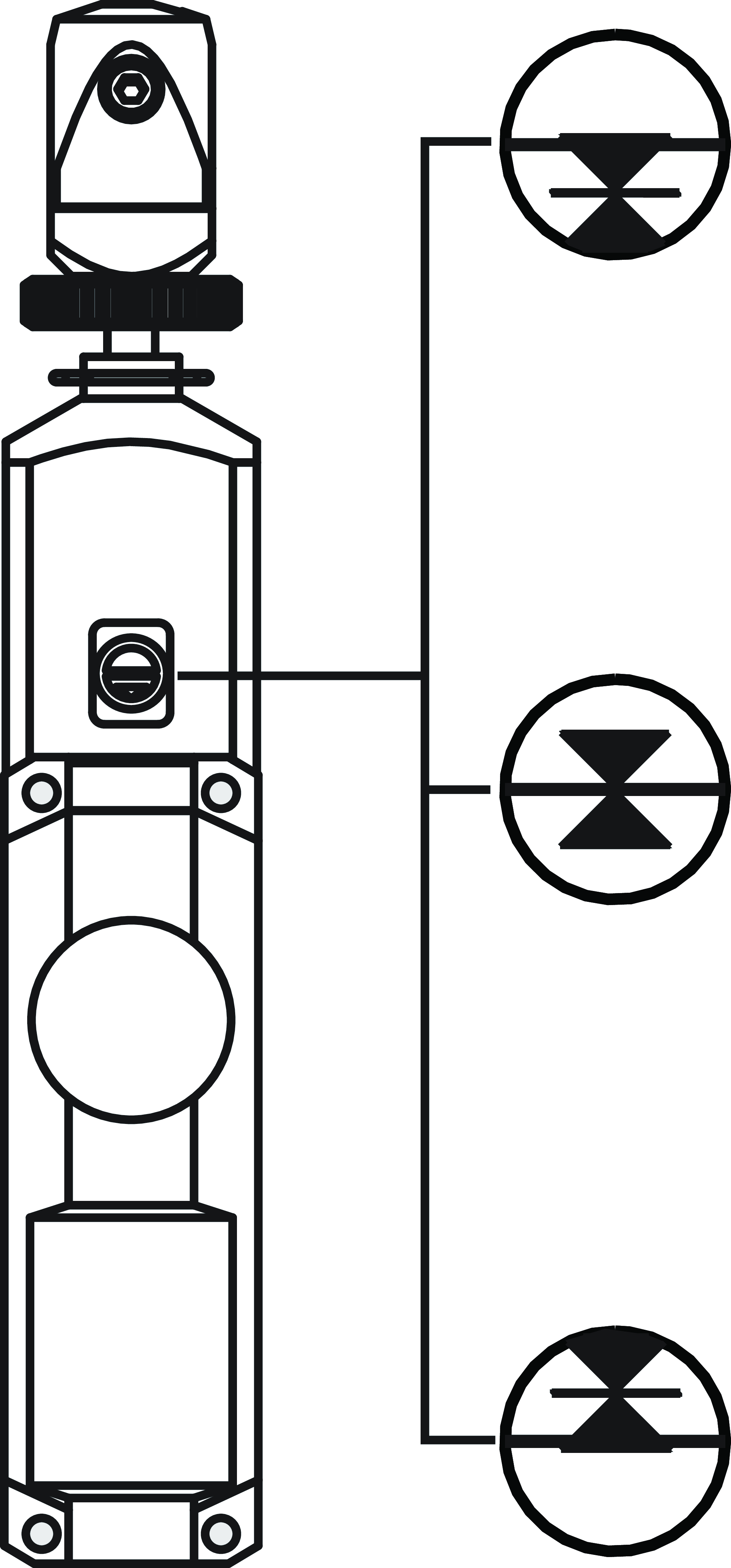
Installation and rope attachment
Attachment
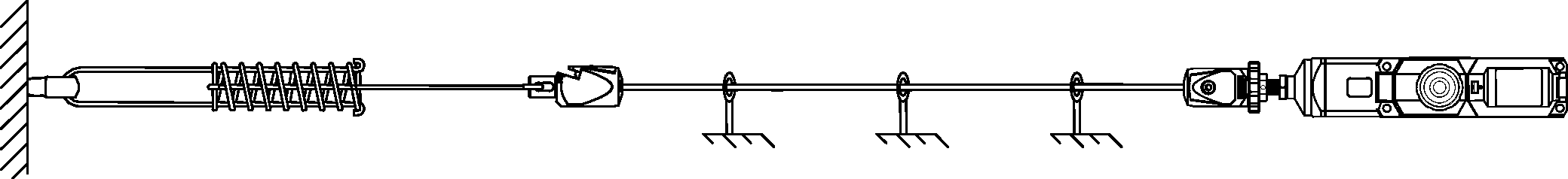
According to EN ISO 13850, EMERGENCY STOP devices must be arranged in such a way that they can be easily reached and safely actuated by people at risk. When using wire ropes - as with rope pull switches - visibility can be improved by means of marking flags.For a proper and safety-compliant version of the pull-wire system, a tensioner spring must be provided on the counter bearing. This enables direction-independent activation at any point along the cable route.
Rope attachment
EUCHNER offers a wide range of accessories for mounting; assembly of the rope pull switches. The pull wire is clamped between the RPS and the counter spring and supported using eyebolts. The support points are set at regular intervals within a few meters.Changes in direction of the steel rope can be realized using rope pulley blocks. Changes of direction up to a maximum of 90° are possible. The advantage of rope pulley blocks is that the frictional forces between the steel cable and the reversal points are kept to a minimum.
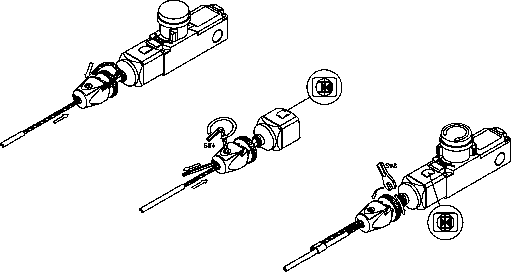
The RPS..SC variants are equipped with a quick-release head that enables the rope to be installed quickly. In addition, the rope tension can be readjusted directly on the quick-release head.
Mounted RPS system:
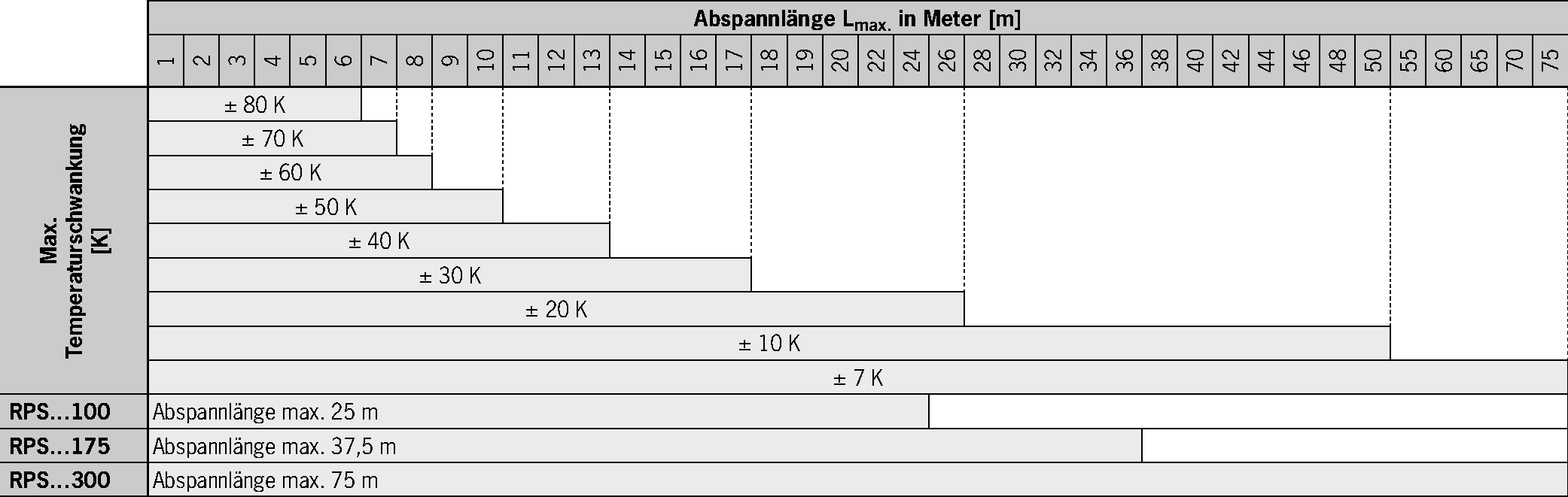
Rope length and temperature dependency
In applications with rope pull switches, the temperature dependency of the entire system must be taken into account in order to avoid unintentional activation due to temperature-related rope elongation or shrinkage. For this purpose, the possible cable length is determined and the trigger point is regularly readjusted.The following diagram illustrates the relationship between rope length and temperature fluctuation. Ideally, mounting; assembly should take place at an ambient temperature of 20°C.
Product finder
Products (47)
No results found
171992
RPS-M-2131SR175M
Rope pull switch with pull-to-reset button for emergency stop device, thimble
RPS-M-2131SR175M
Rope pull switch with pull-to-reset button for emergency stop device, thimble
- Metal housing
- Emergency stop device with detent mechanism as per EN ISO 13850 and EN 60947-5-5
- Thimble for pull wire
- Indication of correct rope tension
- 3 x cable entry M20 x 1.5
- Switching elements with 4 switching contacts
171993
RPS-M-2131SR300M
Rope pull switch with pull-to-reset button for emergency stop device, thimble
RPS-M-2131SR300M
Rope pull switch with pull-to-reset button for emergency stop device, thimble
- Metal housing
- Emergency stop device with detent mechanism as per EN ISO 13850 and EN 60947-5-5
- Thimble for pull wire
- Indication of correct rope tension
- 3 x cable entry M20 x 1.5
- Switching elements with 4 switching contacts
119838
RPS-M-3131SC175BHA10LL024
Rope pull switch with pull-to-reset button for emergency stop device, clamping head, plug connector MR10
RPS-M-3131SC175BHA10LL024
Rope pull switch with pull-to-reset button for emergency stop device, clamping head, plug connector MR10
- Metal housing
- Emergency stop device with detent mechanism as per EN ISO 13850 and EN 60947-5-5
- Clamping head for pull wire
- Indication of correct rope tension
- Plug connector MR10
- LED left
- Switching elements with 4 switching contacts
119841
RPS-M-3131SC175BHA10RL024
Rope pull switch with pull-to-reset button for emergency stop device, clamping head, plug connector MR10
RPS-M-3131SC175BHA10RL024
Rope pull switch with pull-to-reset button for emergency stop device, clamping head, plug connector MR10
- Metal housing
- Emergency stop device with detent mechanism as per EN ISO 13850 and EN 60947-5-5
- Clamping head for pull wire
- Indication of correct rope tension
- Plug connector MR10
- LED right
- Switching elements with 4 switching contacts
114983
RPS-M-3131SC175M
Rope pull switch with pull-to-reset button for emergency stop device, clamping head
RPS-M-3131SC175M
Rope pull switch with pull-to-reset button for emergency stop device, clamping head
- Metal housing
- Emergency stop device with detent mechanism as per EN ISO 13850 and EN 60947-5-5
- Clamping head for pull wire
- Indication of correct rope tension
- 3 x cable entry M20 x 1.5
- Switching elements with 4 switching contacts
119842
RPS-M-3131SC175SFM5
Rope pull switch with pull-to-reset button for emergency stop device, clamping head, plug connector M12
RPS-M-3131SC175SFM5
Rope pull switch with pull-to-reset button for emergency stop device, clamping head, plug connector M12
- Metal housing
- Emergency stop device with detent mechanism as per EN ISO 13850 and EN 60947-5-5
- Clamping head for pull wire
- Indication of correct rope tension
- Plug connector M12, 5-pin
- Switching elements with 4 switching contacts
136351
RPS-M-3131SC175SFM5C2470
Rope pull switch with pull-to-reset button for emergency stop device, clamping head, plug connector M12
RPS-M-3131SC175SFM5C2470
Rope pull switch with pull-to-reset button for emergency stop device, clamping head, plug connector M12
- Metal housing
- Emergency stop device with detent mechanism as per EN ISO 13850 and EN 60947-5-5
- Clamping head for pull wire
- Indication of correct rope tension
- Plug connector M12, 5-pin
- Switching elements with 4 switching contacts
122860
RPS-M-3131SC175SFM5LL024C2424
Rope pull switch with pull-to-reset button for emergency stop device, clamping head, plug connector M12
RPS-M-3131SC175SFM5LL024C2424
Rope pull switch with pull-to-reset button for emergency stop device, clamping head, plug connector M12
- Metal housing
- Emergency stop device with detent mechanism as per EN ISO 13850 and EN 60947-5-5
- Clamping head for pull wire
- Indication of correct rope tension
- Plug connector M12, 5-pin
- LED left
- Switching elements with 4 switching contacts
136352
RPS-M-3131SC175SFM5LL024C2470
Rope pull switch with pull-to-reset button for emergency stop device, clamping head, plug connector M12
RPS-M-3131SC175SFM5LL024C2470
Rope pull switch with pull-to-reset button for emergency stop device, clamping head, plug connector M12
- Metal housing
- Emergency stop device with detent mechanism as per EN ISO 13850 and EN 60947-5-5
- Clamping head for pull wire
- Indication of correct rope tension
- Plug connector M12, 5-pin
- LED left
- Switching elements with 4 switching contacts
122861
RPS-M-3131SC175SFM5RL024C2424
Rope pull switch with pull-to-reset button for emergency stop device, clamping head, plug connector M12
RPS-M-3131SC175SFM5RL024C2424
Rope pull switch with pull-to-reset button for emergency stop device, clamping head, plug connector M12
- Metal housing
- Emergency stop device with detent mechanism as per EN ISO 13850 and EN 60947-5-5
- Clamping head for pull wire
- Indication of correct rope tension
- Plug connector M12, 5-pin
- LED right
- Switching elements with 4 switching contacts
136353
RPS-M-3131SC175SFM5RL024C2470
Rope pull switch with pull-to-reset button for emergency stop device, clamping head, plug connector M12
RPS-M-3131SC175SFM5RL024C2470
Rope pull switch with pull-to-reset button for emergency stop device, clamping head, plug connector M12
- Metal housing
- Emergency stop device with detent mechanism as per EN ISO 13850 and EN 60947-5-5
- Clamping head for pull wire
- Indication of correct rope tension
- Plug connector M12, 5-pin
- LED right
- Switching elements with 4 switching contacts
119839
RPS-M-3131SC300BHA10LL024
Rope pull switch with pull-to-reset button for emergency stop device, clamping head, plug connector MR10
RPS-M-3131SC300BHA10LL024
Rope pull switch with pull-to-reset button for emergency stop device, clamping head, plug connector MR10
- Metal housing
- Emergency stop device with detent mechanism as per EN ISO 13850 and EN 60947-5-5
- Clamping head for pull wire
- Indication of correct rope tension
- Plug connector MR10
- LED left
- Switching elements with 4 switching contacts
119840
RPS-M-3131SC300BHA10RL024
Rope pull switch with pull-to-reset button for emergency stop device, clamping head, plug connector MR10
RPS-M-3131SC300BHA10RL024
Rope pull switch with pull-to-reset button for emergency stop device, clamping head, plug connector MR10
- Metal housing
- Emergency stop device with detent mechanism as per EN ISO 13850 and EN 60947-5-5
- Clamping head for pull wire
- Indication of correct rope tension
- Plug connector MR10
- LED right
- Switching elements with 4 switching contacts
114984
RPS-M-3131SC300M
Rope pull switch with pull-to-reset button for emergency stop device, clamping head
RPS-M-3131SC300M
Rope pull switch with pull-to-reset button for emergency stop device, clamping head
- Metal housing
- Emergency stop device with detent mechanism as per EN ISO 13850 and EN 60947-5-5
- Clamping head for pull wire
- Indication of correct rope tension
- 3 x cable entry M20 x 1.5
- Switching elements with 4 switching contacts
119844
RPS-M-3131SC300SFM5
Rope pull switch with pull-to-reset button for emergency stop device, clamping head, plug connector M12
RPS-M-3131SC300SFM5
Rope pull switch with pull-to-reset button for emergency stop device, clamping head, plug connector M12
- Metal housing
- Emergency stop device with detent mechanism as per EN ISO 13850 and EN 60947-5-5
- Clamping head for pull wire
- Indication of correct rope tension
- Plug connector M12, 5-pin
- Switching elements with 4 switching contacts
114981
RPS-M-E-3131SC175M
Rope pull switch with pull-to-reset button for emergency stop device, clamping head, with pre-failure monitoring
RPS-M-E-3131SC175M
Rope pull switch with pull-to-reset button for emergency stop device, clamping head, with pre-failure monitoring
- Metal housing
- Emergency stop device with detent mechanism as per EN ISO 13850 and EN 60947-5-5
- Clamping head for pull wire
- Indication of correct rope tension
- 3 x cable entry M20 x 1.5
- Switching elements with 4 switching contacts
- Pre-failure monitoring for the rope tension
114982
RPS-M-E-3131SC300M
Rope pull switch with pull-to-reset button for emergency stop device, clamping head, with pre-failure monitoring
RPS-M-E-3131SC300M
Rope pull switch with pull-to-reset button for emergency stop device, clamping head, with pre-failure monitoring
- Metal housing
- Emergency stop device with detent mechanism as per EN ISO 13850 and EN 60947-5-5
- Clamping head for pull wire
- Indication of correct rope tension
- 3 x cable entry M20 x 1.5
- Switching elements with 4 switching contacts
- Pre-failure monitoring for the rope tension
094852
RPS2131PC100M
Rope pull switch with pull-to-reset button for EMERGENCY STOP device, clamping head
RPS2131PC100M
Rope pull switch with pull-to-reset button for EMERGENCY STOP device, clamping head
- Plastic housing
- Emergency stop device with detent mechanism as per EN ISO 13850 and EN 60947-5-5
- Clamping head for pull wire
- Indication of correct rope tension
- 3 x cable entry M20 x 1.5
- Switching elements with 4 switching contacts
- Blue reset button
094854
RPS2131PC300M
Rope pull switch with pull-to-reset button for EMERGENCY STOP device, clamping head
RPS2131PC300M
Rope pull switch with pull-to-reset button for EMERGENCY STOP device, clamping head
- Plastic housing
- Emergency stop device with detent mechanism as per EN ISO 13850 and EN 60947-5-5
- Clamping head for pull wire
- Indication of correct rope tension
- 3 x cable entry M20 x 1.5
- Switching elements with 4 switching contacts
- Blue reset button
094849
RPS2131PR100M
Rope pull switch with pull-to-reset button for EMERGENCY STOP device, pull lug
RPS2131PR100M
Rope pull switch with pull-to-reset button for EMERGENCY STOP device, pull lug
- Plastic housing
- Emergency stop device with detent mechanism as per EN ISO 13850 and EN 60947-5-5
- Rope clamp for pull wire
- Indication of correct rope tension
- 3 x cable entry M20 x 1.5
- Switching elements with 4 switching contacts
- Blue reset button
094851
RPS2131PR300M
Rope pull switch with pull-to-reset button for EMERGENCY STOP device, pull lug
RPS2131PR300M
Rope pull switch with pull-to-reset button for EMERGENCY STOP device, pull lug
- Plastic housing
- Emergency stop device with detent mechanism as per EN ISO 13850 and EN 60947-5-5
- Rope clamp for pull wire
- Indication of correct rope tension
- 3 x cable entry M20 x 1.5
- Switching elements with 4 switching contacts
- Blue reset button
094430
RPS2131SC100M
Rope pull switch with pull-to-reset button for EMERGENCY STOP device, clamping head
RPS2131SC100M
Rope pull switch with pull-to-reset button for EMERGENCY STOP device, clamping head
- Plastic housing
- Emergency stop device with detent mechanism as per EN ISO 13850 and EN 60947-5-5
- Clamping head for pull wire
- Indication of correct rope tension
- 3 x cable entry M20 x 1.5
- Switching elements with 4 switching contacts
- Emergency stop
094431
RPS2131SC175M
Rope pull switch with pull-to-reset button for EMERGENCY STOP device, clamping head
RPS2131SC175M
Rope pull switch with pull-to-reset button for EMERGENCY STOP device, clamping head
- Plastic housing
- Emergency stop device with detent mechanism as per EN ISO 13850 and EN 60947-5-5
- Clamping head for pull wire
- Indication of correct rope tension
- 3 x cable entry M20 x 1.5
- Switching elements with 4 switching contacts
- Emergency stop
088885
RPS3131PC100M
Rope pull switch with pull-to-reset button for EMERGENCY STOP device, clamping head
RPS3131PC100M
Rope pull switch with pull-to-reset button for EMERGENCY STOP device, clamping head
- Plastic housing
- Emergency stop device with detent mechanism as per EN ISO 13850 and EN 60947-5-5
- Clamping head for pull wire
- Indication of correct rope tension
- 3 x cable entry M20 x 1.5
- Switching elements with 4 switching contacts
- Blue reset button
088886
RPS3131PC175M
Rope pull switch with pull-to-reset button for EMERGENCY STOP device, clamping head
RPS3131PC175M
Rope pull switch with pull-to-reset button for EMERGENCY STOP device, clamping head
- Plastic housing
- Emergency stop device with detent mechanism as per EN ISO 13850 and EN 60947-5-5
- Clamping head for pull wire
- Indication of correct rope tension
- 3 x cable entry M20 x 1.5
- Switching elements with 4 switching contacts
- Blue reset button
088887
RPS3131PC300M
Rope pull switch with pull-to-reset button for EMERGENCY STOP device, clamping head
RPS3131PC300M
Rope pull switch with pull-to-reset button for EMERGENCY STOP device, clamping head
- Plastic housing
- EMERGENCY STOP device with detent mechanism according to EN ISO 13850 and EN 60947-5-5
- Clamping head for pull wire
- Indication of correct rope tension
- 3 x cable entry M20 x 1.5
- Switching elements with 4 switching contacts
- Blue reset button
167912
RPS3131PC300SFM5C2626
Rope pull switch with pull-to-reset button for EMERGENCY STOP device, clamping head
RPS3131PC300SFM5C2626
Rope pull switch with pull-to-reset button for EMERGENCY STOP device, clamping head
- Plastic housing
- Emergency stop device with detent mechanism as per EN ISO 13850 and EN 60947-5-5
- Clamping head for pull wire
- Indication of correct rope tension
- Plug connector M12, 5-pin
- Switching elements with 2 switching contacts
- Blue reset button
088888
RPS3131PR100M
Rope pull switch with pull-to-reset button for EMERGENCY STOP device, pull lug
RPS3131PR100M
Rope pull switch with pull-to-reset button for EMERGENCY STOP device, pull lug
- Plastic housing
- EMERGENCY STOP device with detent mechanism according to EN ISO 13850 and EN 60947-5-5
- Rope clamp for pull wire
- Indication of correct rope tension
- 3 x cable entry M20 x 1.5
- Switching elements with 4 switching contacts
- Blue reset button
088889
RPS3131PR175M
Rope pull switch with pull-to-reset button for EMERGENCY STOP device, pull lug
RPS3131PR175M
Rope pull switch with pull-to-reset button for EMERGENCY STOP device, pull lug
- Plastic housing
- Emergency stop device with detent mechanism as per EN ISO 13850 and EN 60947-5-5
- Rope clamp for pull wire
- Indication of correct rope tension
- 3 x cable entry M20 x 1.5
- Switching elements with 4 switching contacts
- Blue reset button
088890
RPS3131PR300M
Rope pull switch with pull-to-reset button for EMERGENCY STOP device, pull lug
RPS3131PR300M
Rope pull switch with pull-to-reset button for EMERGENCY STOP device, pull lug
- Plastic housing
- Emergency stop device with detent mechanism as per EN ISO 13850 and EN 60947-5-5
- Rope clamp for pull wire
- Indication of correct rope tension
- 3 x cable entry M20 x 1.5
- Switching elements with 4 switching contacts
- Blue reset button
094083
RPS3131SC100BHA10LL024
Rope pull switch with pull-to-reset button for EMERGENCY STOP device, clamping head, plug connector MR10
RPS3131SC100BHA10LL024
Rope pull switch with pull-to-reset button for EMERGENCY STOP device, clamping head, plug connector MR10
- Plastic housing
- Emergency stop device with detent mechanism as per EN ISO 13850 and EN 60947-5-5
- Clamping head for pull wire
- Indication of correct rope tension
- Plug connector MR10
- LED left
- Switching elements with 4 switching contacts
- Emergency stop
094084
RPS3131SC100BHA10RL024
Rope pull switch with pull-to-reset button for EMERGENCY STOP device, clamping head, plug connector MR10
RPS3131SC100BHA10RL024
Rope pull switch with pull-to-reset button for EMERGENCY STOP device, clamping head, plug connector MR10
- Plastic housing
- Emergency stop device with detent mechanism as per EN ISO 13850 and EN 60947-5-5
- Clamping head for pull wire
- Indication of correct rope tension
- Plug connector MR10
- LED right
- Switching elements with 4 switching contacts
- Emergency stop
111491
RPS3131SC100LSFM5
Rope pull switch with pull-to-reset button for EMERGENCY STOP device, clamping head, plug connector M12
RPS3131SC100LSFM5
Rope pull switch with pull-to-reset button for EMERGENCY STOP device, clamping head, plug connector M12
- Plastic housing
- Emergency stop device with detent mechanism as per EN ISO 13850 and EN 60947-5-5
- Clamping head for pull wire
- Indication of correct rope tension
- Plug connector(s) M12, 5-pin left
- Switching elements with 2 switching contacts
- Emergency stop
088882
RPS3131SC100M
Rope pull switch with pull-to-reset button for EMERGENCY STOP device, clamping head
RPS3131SC100M
Rope pull switch with pull-to-reset button for EMERGENCY STOP device, clamping head
- Plastic housing
- Emergency stop device with detent mechanism as per EN ISO 13850 and EN 60947-5-5
- Clamping head for pull wire
- Indication of correct rope tension
- 3 x cable entry M20 x 1.5
- Switching elements with 4 switching contacts
- Emergency stop
111490
RPS3131SC100RSFM5
Rope pull switch with pull-to-reset button for EMERGENCY STOP device, clamping head, plug connector M12
RPS3131SC100RSFM5
Rope pull switch with pull-to-reset button for EMERGENCY STOP device, clamping head, plug connector M12
- Plastic housing
- Emergency stop device with detent mechanism as per EN ISO 13850 and EN 60947-5-5
- Clamping head for pull wire
- Indication of correct rope tension
- Plug connector(s) M12, 5-pin right
- Switching elements with 2 switching contacts
- Emergency stop
110450
RPS3131SC100SFM5
Rope pull switch with pull-to-reset button for EMERGENCY STOP device, clamping head, plug connector M12
RPS3131SC100SFM5
Rope pull switch with pull-to-reset button for EMERGENCY STOP device, clamping head, plug connector M12
- Plastic housing
- Emergency stop device with detent mechanism as per EN ISO 13850 and EN 60947-5-5
- Clamping head for pull wire
- Indication of correct rope tension
- Plug connector M12, 5-pin
- Switching elements with 2 switching contacts
- Emergency stop
094085
RPS3131SC175BHA10LL024
Rope pull switch with pull-to-reset button for EMERGENCY STOP device, clamping head, plug connector MR10
RPS3131SC175BHA10LL024
Rope pull switch with pull-to-reset button for EMERGENCY STOP device, clamping head, plug connector MR10
- Plastic housing
- EMERGENCY STOP device with detent mechanism according to EN ISO 13850 and EN 60947-5-5
- Clamping head for pull wire
- Indication of correct rope tension
- Plug connector MR10
- LED left
- Switching elements with 4 switching contacts
- Emergency stop
094086
RPS3131SC175BHA10RL024
Rope pull switch with pull-to-reset button for EMERGENCY STOP device, clamping head, plug connector MR10
RPS3131SC175BHA10RL024
Rope pull switch with pull-to-reset button for EMERGENCY STOP device, clamping head, plug connector MR10
- Plastic housing
- Emergency stop device with detent mechanism as per EN ISO 13850 and EN 60947-5-5
- Clamping head for pull wire
- Indication of correct rope tension
- Plug connector MR10
- LED right
- Switching elements with 4 switching contacts
- Emergency stop
111493
RPS3131SC175LSFM5
Rope pull switch with pull-to-reset button for EMERGENCY STOP device, clamping head, plug connector M12
RPS3131SC175LSFM5
Rope pull switch with pull-to-reset button for EMERGENCY STOP device, clamping head, plug connector M12
- Plastic housing
- EMERGENCY STOP device with detent mechanism according to EN ISO 13850 and EN 60947-5-5
- Clamping head for pull wire
- Indication of correct rope tension
- Plug connector(s) M12, 5-pin left
- Switching elements with 2 switching contacts
- Emergency stop
088883
RPS3131SC175M
Rope pull switch with pull-to-reset button for EMERGENCY STOP device, clamping head
RPS3131SC175M
Rope pull switch with pull-to-reset button for EMERGENCY STOP device, clamping head
- Plastic housing
- Emergency stop device with detent mechanism as per EN ISO 13850 and EN 60947-5-5
- Clamping head for pull wire
- Indication of correct rope tension
- 3 x cable entry M20 x 1.5
- Switching elements with 4 switching contacts
- Emergency stop
111492
RPS3131SC175RSFM5
Rope pull switch with pull-to-reset button for EMERGENCY STOP device, clamping head, plug connector M12
RPS3131SC175RSFM5
Rope pull switch with pull-to-reset button for EMERGENCY STOP device, clamping head, plug connector M12
- Plastic housing
- EMERGENCY STOP device with detent mechanism according to EN ISO 13850 and EN 60947-5-5
- Clamping head for pull wire
- Indication of correct rope tension
- Plug connector(s) M12, 5-pin right
- Switching elements with 2 switching contacts
- Emergency stop
110451
RPS3131SC175SFM5
Rope pull switch with pull-to-reset button for EMERGENCY STOP device, clamping head, plug connector M12
RPS3131SC175SFM5
Rope pull switch with pull-to-reset button for EMERGENCY STOP device, clamping head, plug connector M12
- Plastic housing
- EMERGENCY STOP device with detent mechanism according to EN ISO 13850 and EN 60947-5-5
- Clamping head for pull wire
- Indication of correct rope tension
- Plug connector M12, 5-pin
- Switching elements with 2 switching contacts
- Emergency stop
094087
RPS3131SC300BHA10LL024
Rope pull switch with pull-to-reset button for EMERGENCY STOP device, clamping head, plug connector MR10
RPS3131SC300BHA10LL024
Rope pull switch with pull-to-reset button for EMERGENCY STOP device, clamping head, plug connector MR10
- Plastic housing
- Emergency stop device with detent mechanism as per EN ISO 13850 and EN 60947-5-5
- Clamping head for pull wire
- Indication of correct rope tension
- Plug connector MR10
- LED left
- Switching elements with 4 switching contacts
- Emergency stop
094088
RPS3131SC300BHA10RL024
Rope pull switch with turn-to-reset button for EMERGENCY STOP device, clamping head, plug connector MR10
RPS3131SC300BHA10RL024
Rope pull switch with turn-to-reset button for EMERGENCY STOP device, clamping head, plug connector MR10
- Plastic housing
- EMERGENCY STOP device with detent mechanism according to EN ISO 13850 and EN 60947-5-5
- Clamping head for pull wire
- Indication of correct rope tension
- Plug connector MR10
- LED right
- Switching elements with 4 switching contacts
- Emergency stop
088884
RPS3131SC300M
Rope pull switch with pull-to-reset button for EMERGENCY STOP device, clamping head
RPS3131SC300M
Rope pull switch with pull-to-reset button for EMERGENCY STOP device, clamping head
- Plastic housing
- Emergency stop device with detent mechanism as per EN ISO 13850 and EN 60947-5-5
- Clamping head for pull wire
- Indication of correct rope tension
- 3 x cable entry M20 x 1.5
- Switching elements with 4 switching contacts
- Emergency stop
110452
RPS3131SC300SFM5
Rope pull switch with pull-to-reset button for EMERGENCY STOP device, clamping head, plug connector M12
RPS3131SC300SFM5
Rope pull switch with pull-to-reset button for EMERGENCY STOP device, clamping head, plug connector M12
- Plastic housing
- EMERGENCY STOP device with detent mechanism according to EN ISO 13850 and EN 60947-5-5
- Clamping head for pull wire
- Indication of correct rope tension
- Plug connector M12, 5-pin
- Switching elements with 2 switching contacts
- Emergency stop
167913
RPS3131SC300SFM5C2626
Rope pull switch with pull-to-reset button for EMERGENCY STOP device, clamping head, plug connector M12
RPS3131SC300SFM5C2626
Rope pull switch with pull-to-reset button for EMERGENCY STOP device, clamping head, plug connector M12
- Plastic housing
- EMERGENCY STOP device with detent mechanism according to EN ISO 13850 and EN 60947-5-5
- Clamping head for pull wire
- Indication of correct rope tension
- Plug connector M12, 5-pin
- Switching elements with 2 switching contacts
- Emergency stop