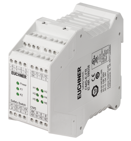
CMS-E-FR (Order no. 099258)
Choose content
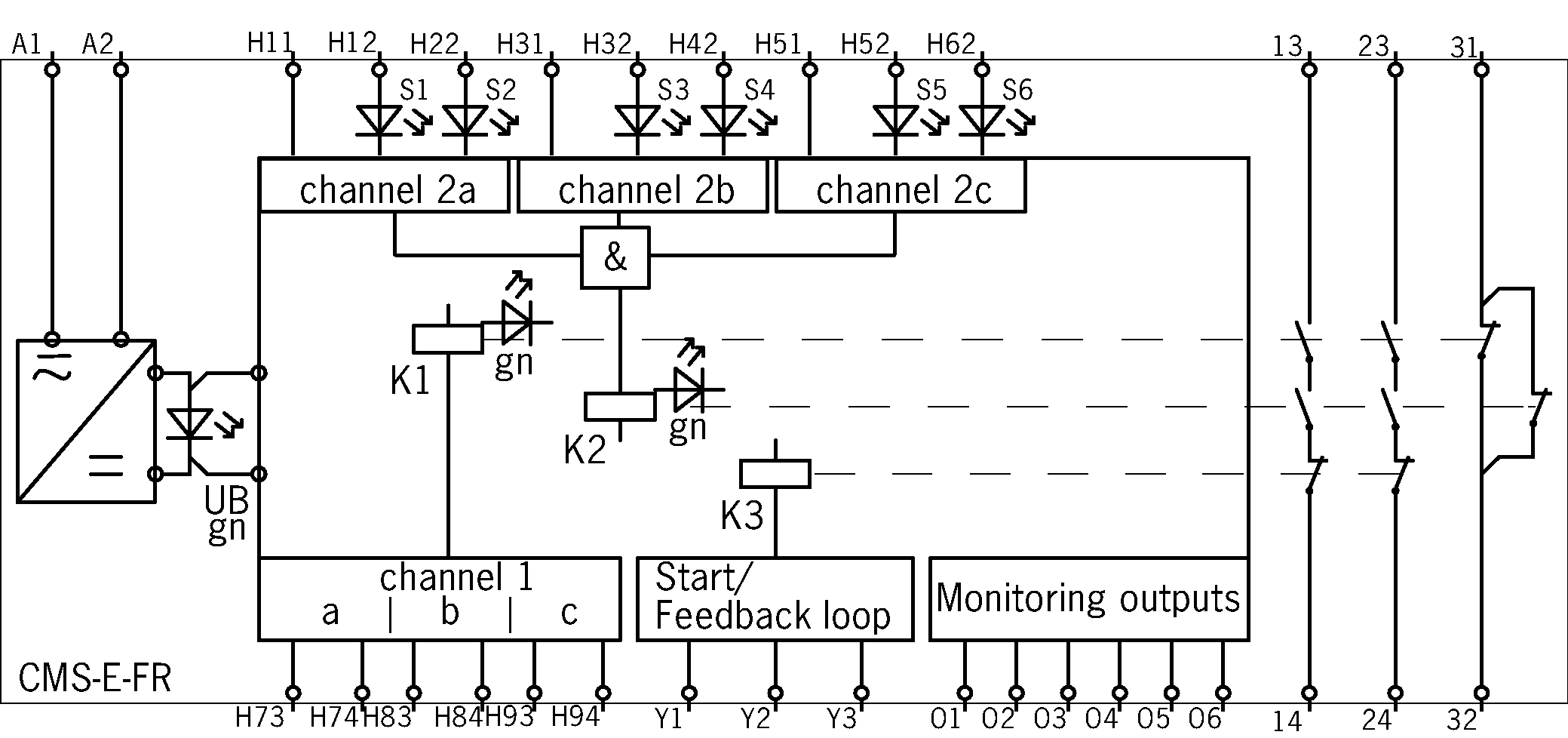
Evaluation unit CMS-E-FR, 2 safety contacts, 1 auxiliary contact, 6 monitoring outputs, 1 feedback loop can be connected
- Up to 6 read heads can be connected
- 2 safety contacts
- 1 auxiliary contact
- 6 monitoring outputs
- 1 feedback loop can be connected
- Start automatic/monitored/not monitored
Description
Functional description
The evaluation unit CMS-E-FR is suitable for the direct connection of up to 6 read heads.
Category/PL according to EN ISO 13849-1
- Category 4/PL e with only one read head connected
- Max. category 3/PL d with more than one read head connected
Notice:
At low approach speeds in the z direction, the time between the switching of the reed contacts must not be more than 0.6 ms.
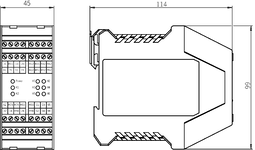
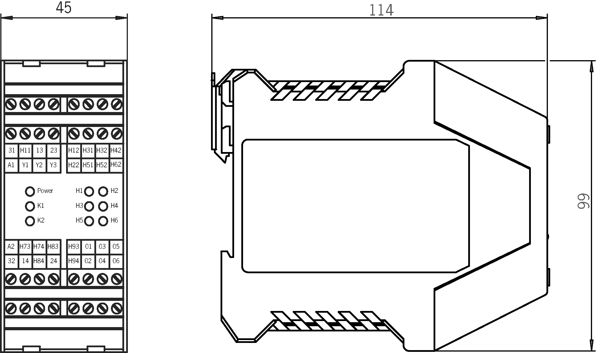
Dimensional drawings
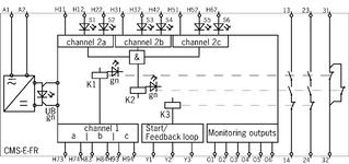
Connection examples
Technical data
Approvals


Operating and display elements
| LED display | 1 indicator LED Power, 2 output LEDs and 6 status indicators for the read heads |
Electrical connection values
| Fuse | |||||||||||||||||
| Protection internal (operating voltage UB) | 0.75 A Automatically resetting fuse PTC | ||||||||||||||||
| Safety contacts 13/14, 23/24 | 4 A gG (External contact fuse (safety circuit) acc. to EN IEC 60269-1) | ||||||||||||||||
| Connection cross section | 0.14 ... 2.5 mm² | Outputs | |||||||||||||||
| |||||||||||||||||
| Rated insulation voltage Ui | 250 V | ||||||||||||||||
| Operating voltage | |||||||||||||||||
| AC/DC | 24 V -10% ... +10% (All the electrical connections must either be isolated from the mains supply by a safety transformer according to EN 61558-2-6 with limited output voltage in the event of a fault, or by other equivalent insulation measures.) | ||||||||||||||||
| Utilization category | |||||||||||||||||
| AC-15 | 0.9 A 240 V and 0.9 A, 24 V (Max. switching current per contact) | ||||||||||||||||
| AC-1 | 3A, 230V ; 3A , 24V (Max. switching current per contact) | ||||||||||||||||
| DC-13 | 1.5A, 24V (max. switching current) | ||||||||||||||||
| Risk time according to EN 60947-5-3 | max. 20 ms | ||||||||||||||||
| Switching load | |||||||||||||||||
| According to UL class 2 | Input: 24 V AC/DC; output: 30 V AC, 24 V DC | ||||||||||||||||
| Switching capacity (VA) | |||||||||||||||||
| Safety contacts 13/14, 23/24 | max. 720 VA | ||||||||||||||||
| Switching voltage | |||||||||||||||||
| Safety contacts 13/14, 23/24 | max. AC 240 V | ||||||||||||||||
| Switching current | |||||||||||||||||
| Semiconductor outputs 01 to 06 | 50 mA at DC 24 V (per monitoring output 01 to 06 mA) | ||||||||||||||||
| Safety contacts 13/14, 23/24 | 10 ... 3000 mA at DC 24 V | ||||||||||||||||
| Auxiliary contacts 31/32 | max. 1500 mA at DC 24 V | ||||||||||||||||
| Current consumption | |||||||||||||||||
| at UB = 24 V DC | 10 ... 120 mA | ||||||||||||||||
| Degree of contamination (external, according to EN 60947-1) | 2 | ||||||||||||||||
Mechanical values and environment
| Approach direction | Z (If the approach speed is low, the approach direction Z should be avoided.) |
| Connection type | Connection terminals |
| Storage temperature | -25 ... 70 °C |
| Mechanical life | 10 x 10⁶ |
| Mounting type | Mounting rail TH 35 (EN IEC 60715) |
| Degree of protection | Terminals IP20 / housing IP40 |
| Ambient temperature | 0 ... 55 °C |
| Material | |
| Housing | Polyamide PA6.6 |
Characteristic values according to EN ISO 13849-1 and EN IEC 62061
| PL | Maximum SIL | PFHD | Category | Mission time | ||
|---|---|---|---|---|---|---|
| Monitoring of the guard position | with 1 read head | PL e | - | 2.5x10⁻⁸ | 4 | 20 y |
| Only applies with switching voltage 24V DC and switching current up to 0.1 A (max. switching cycles 166,000 1/y) OR up to 1 A (max. switching cycles 70,000 1/y) | ||||||
| with >1 read head | PL d | - | 1x10⁻⁷ | 3 | 20 y | |
| Only applies with switching voltage 24V DC and switching current up to 0.1 A (max. switching cycles 166,000 1/y) OR up to 1 A (max. switching cycles 70,000 1/y) | ||||||
Miscellaneous
| in compliance with | EN ISO 13849-1: 2015; EN ISO 13849-2:2012; EN 50178: 1997; EN 60204-1: 2006/A1: 2009; EN ISO 13850: 2015; EN 14119: 2013; EN 6100-2-6: 2005; EN 6100-6-3: 2007/A1: 2011; EN 60947-5-3: 2013 |
In combination with read head CMS-R-AXH-03V, CMS-R-AXH-05V, CMS-R-AXH-SC, CMS-R-AXH-05P and actuator CMS-M-AC
| Secured switch-off distance sar | max. 31 mm (The assured release distance s_ar corresponds to the reset distance.) |
| Secured switching distance sao | |
| with center offset m=0 | min. 6 mm (Figure only applies if there is no ferromagnetic material in the vicinity of the read head and the actuator.) |
| Center offset | |
| at s =3 mm read distance | 2.5 mm 2.5 mm (Figure only applies if there is no ferromagnetic material in the vicinity of the read head and the actuator.) |
In combination with read head CMS-RH-BYB-03VL, CMS-RH-BYB-05VL and actuator CMS-MH-BB
| Secured switch-off distance sar | max. 13 mm (The assured release distance s_ar corresponds to the reset distance.) |
| Secured switching distance sao | |
| with center offset m=0 | min. 6 mm (Figure only applies if there is no ferromagnetic material in the vicinity of the read head and the actuator.) |
| Center offset | |
| at s =3 mm read distance | 2.5 mm (Figure only applies if there is no ferromagnetic material in the vicinity of the read head and the actuator.) |
In combination with read head CMS-R-EXM-03V, CMS-R-EXM-05V, CMS-R-EXM-SC and actuator CMS-M-EF
| Secured switch-off distance sar | max. 17 mm (The assured release distance s_ar corresponds to the reset distance.) |
| Secured switching distance sao | |
| with center offset m=0 | min. 6 mm (Figure only applies if there is no ferromagnetic material in the vicinity of the read head and the actuator.) |
| Center offset | |
| at s =3 mm read distance | 2.5 mm 2.5 mm (Figure only applies if there is no ferromagnetic material in the vicinity of the read head and the actuator.) |
In combination with read head CMS-R-CXC-03V, CMS-R-CXC-05V, CMS-R-CXC-05P, CMS-R-CXC-SC and actuator CMS-M-CA
| Secured switch-off distance sar | max. 14 mm (The assured release distance s_ar corresponds to the reset distance.) |
| Secured switching distance sao | |
| with center offset m=0 | min. 6 mm (Figure only applies if there is no ferromagnetic material in the vicinity of the read head and the actuator.) |
| Center offset | |
| at s =3 mm read distance | 2.5 mm 2.5 mm (Figure only applies if there is no ferromagnetic material in the vicinity of the read head and the actuator.) |
In combination with read head CMS-RH-AYA-03VL, CMS-RH-AYA-05VL and actuator CMS-MH-AA
| Secured switch-off distance sar | max. 20 mm (The assured release distance s_ar corresponds to the reset distance.) |
| Secured switching distance sao | |
| with center offset m=0 | min. 10 mm (Figure only applies if there is no ferromagnetic material in the vicinity of the read head and the actuator.) |
| Center offset | |
| at s =3 mm read distance | 2.5 mm 2.5 mm (Figure only applies if there is no ferromagnetic material in the vicinity of the read head and the actuator.) |
In combination with read head CMS-R-BXI-03V, CMS-R-BXI-05V, CMS-R-BXI-SC, CMS-R-BXI-07P and actuator CMS-M-BD
| Secured switch-off distance sar | max. 12 mm (The assured release distance s_ar corresponds to the reset distance.) |
| Secured switching distance sao | |
| with center offset m=0 | min. 3 mm (Figure only applies if there is no ferromagnetic material in the vicinity of the read head and the actuator.) |
| Center offset | |
| at s =3 mm read distance | 2.5 mm (Figure only applies if there is no ferromagnetic material in the vicinity of the read head and the actuator.) |
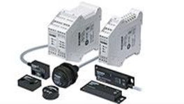
Accessories
CMS read heads


Downloads
Complete package
Download all important documents with a single click.
Content:
- The operating instructions and any additions to the operating instructions or brief instructions
- Any data sheets to supplement the operating instructions
- The declaration of conformity
Download Complete Package (ZIP, 2,4 MB)
Single Documents
Declarations of conformity
EU-Konformitätserklärung

Doc. no.
Version
Language
Size
EU-Konformitätserklärung
Doc. no.
EDC2112987
Version
Language
Size
0,2 MB
UKCA-Konformitätserklärung

Doc. no.
Version
Language
Size
UKCA-Konformitätserklärung
Doc. no.
EDC20001569
Version
Language
Size
0,1 MB
Instructions
Operating Instructions Evaluation Unit CMS-E-FR


Doc. no.
Version
Language
Size
Operating Instructions Evaluation Unit CMS-E-FR
Doc. no.
2102345
Version
11/25
Language
Size
0,8 MB
Mode d’emploi Analyseur CMS-E-FR
Doc. no.
2102345
Version
11/25
Language
Size
0,8 MB
Manual de instrucciones Unidad de evaluación CMS-E-FR
Doc. no.
2102345
Version
11/25
Language
Size
0,8 MB
Betriebsanleitung Auswertegerät CMS-E-FR
Doc. no.
2102345
Version
11/25
Language
Size
0,8 MB

Other Documents
Approvals and certificates
TÜV SÜD Italia_CMS-E-E(F)R_TUV IT 0948 25 MAC 480 B

Doc. no.
Version
Language
Size
TÜV SÜD Italia_CMS-E-E(F)R_TUV IT 0948 25 MAC 480 B
Doc. no.
Version
Language
Size
1,1 MB
WEEE

Doc. no.
Version
Language
Size
WEEE
Doc. no.
ECO20001806
Version
Language
Size
0,1 MB
c UL us

Doc. no.
Version
Language
Size
c UL us
Doc. no.
Version
Language
Size
1,0 MB
Sales documents
Interrupteurs de sécurité à codage magnétique CMS

Doc. no.
Version
Language
Size
Interrupteurs de sécurité à codage magnétique CMS
Doc. no.
090606
Version
10-11/20
Language
Size
5,8 MB


CAD/eCAD

Ordering data
| Ordernumber | 099258 |
| Item designation | CMS-E-FR |
| Gross weight | 0,349kg |
| Customs tariff number | 85364110 |
| ECLASS | 27-27-24-02 Safety-related magnetic proximity switch |